
Condensing Gas Boilers Troubleshooting
These pages are used for screening Greenstar Boiler error codes.
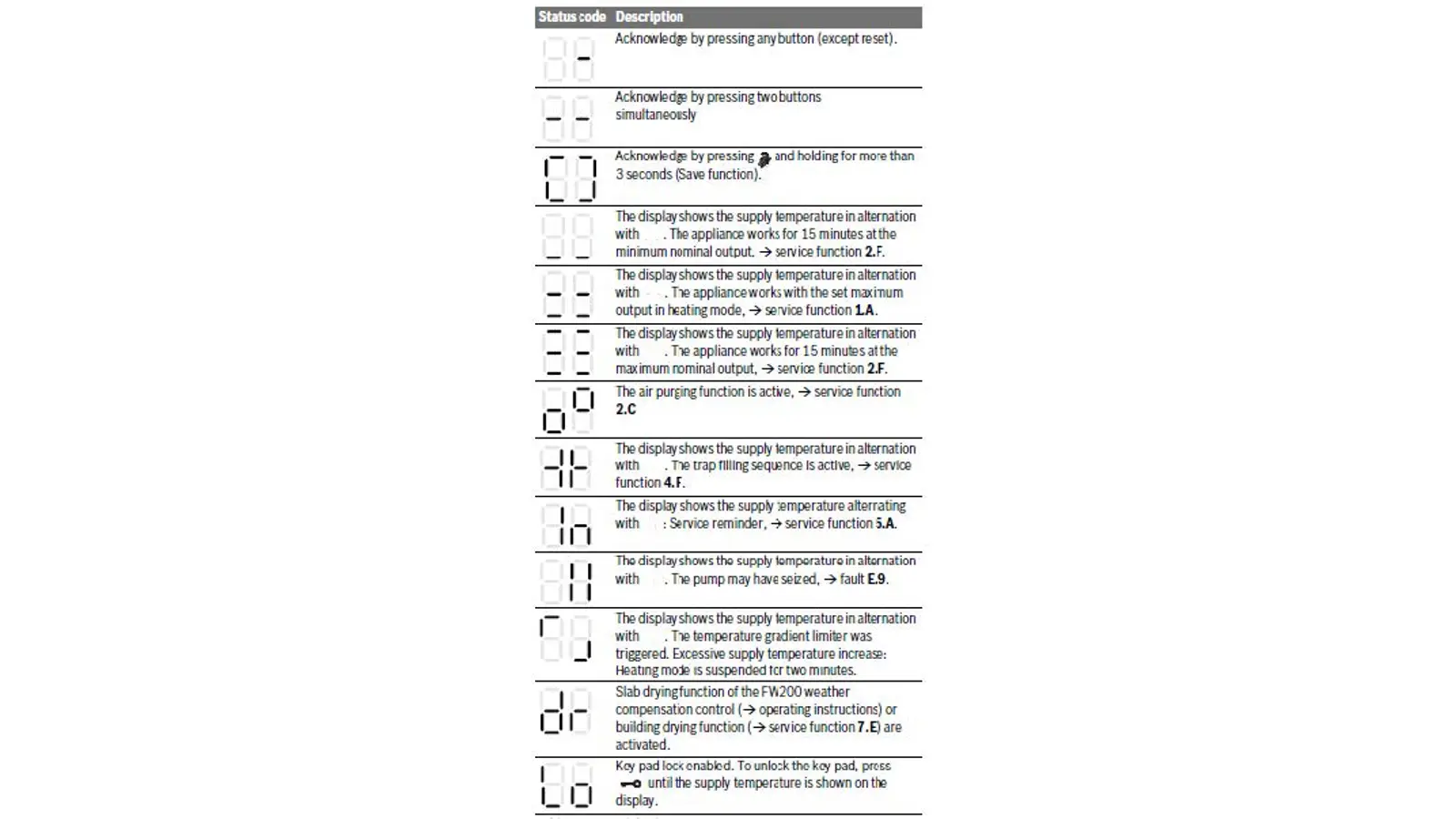
The icons below may be on the display, however they are not error codes.
0Y Error Code
0Y Error Code
Digital Multi-meter
Hand Tools
Thermometer
Error Code Information
| Models | GB142/24, GB142/30, GB142/45, GB142/60 |
| Error Code | 0Y |
| Error Code Meaning |
This code indicates the boiler has reached its temperature limit. The limit will be based on settings and application. |
| Possible Causes |
A warm day if running an outdoor reset curve. An issue with a circulation pump. A bad return temperature sensor. Boiler too big and not enough radiation. |
Troubleshooting Steps
Step 1. Ohm out the return sensor.
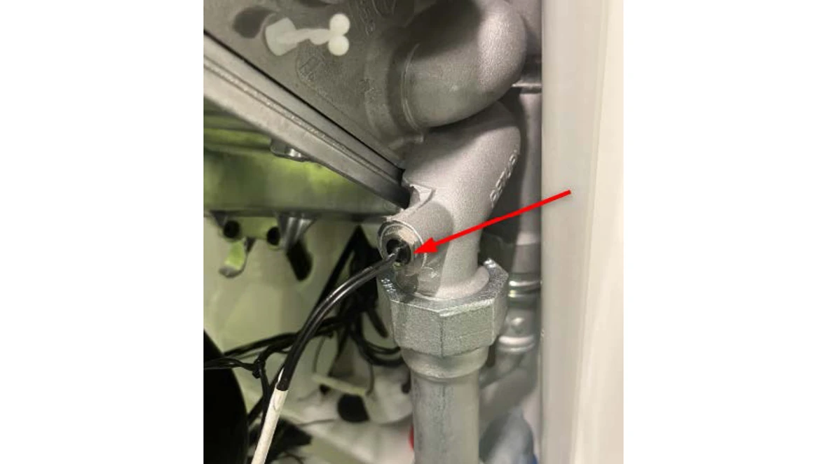
- Locate the return sensor on the right side of the boiler.
- There are two sensors on the right side of the boiler, the return is the one that is lowest.
- Follow the black wires from the sensor to the white plastic plug and disconnect the wires.
- Using a digital multi-meter, ohm out the sensor side of the disconnect.
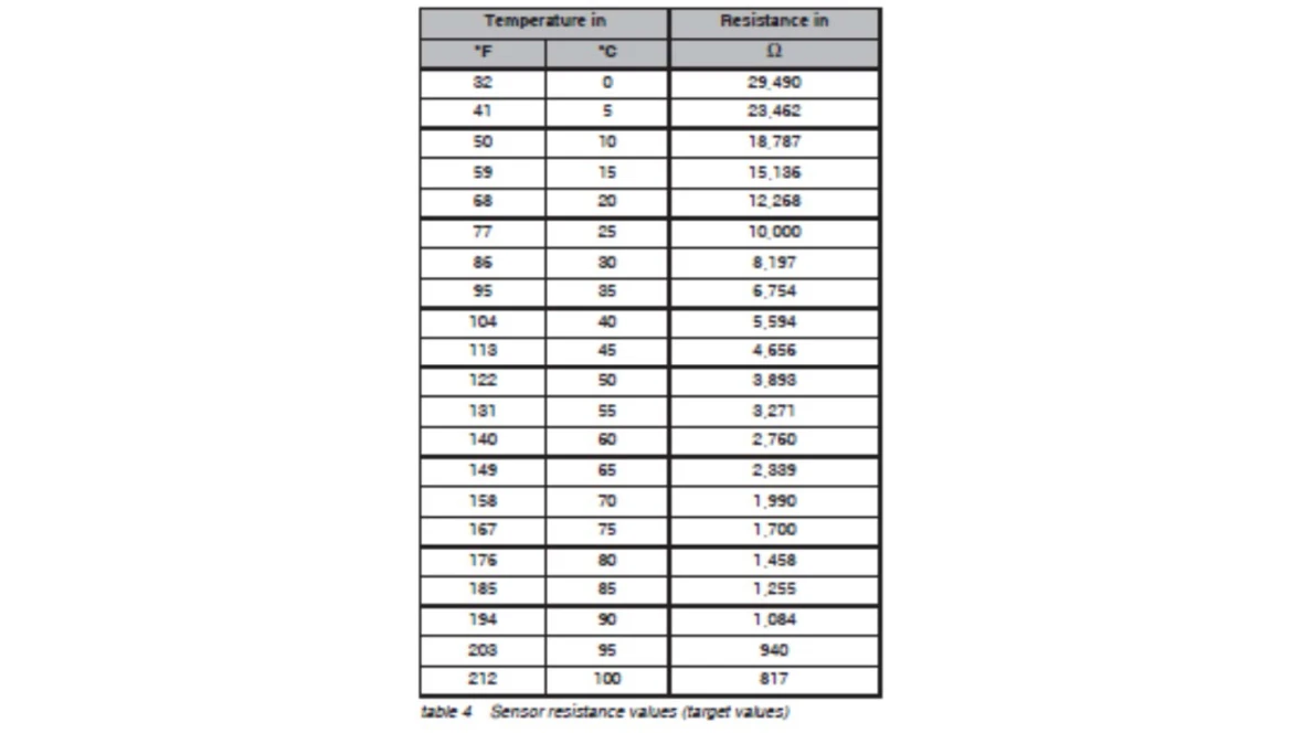
- Compare the ohm reading to the temperature reading of the pipe using the chart from the back of the manual.
Results:
- If the ohm reading matches the temperature reading in the chart, the sensor is good. Contact a Bosch Technical Support Specialist
- If the ohm reading doesn't match the temperature reading in the chart, the sensor is bad.
- Replace the sensor. The part number is available through the Aftermarket Resource Center.
1C Error Code
1C Error Code
Tools Needed
Hand Tools
Error Code Information
| Models | GB142/24, GB142/30, GB142/45, GB142/60 |
| Error Code | 1C |
| Error Code Meaning | Jumper in wire harness is disconnected or broken |
| Possible Causes |
Broken wire Loose Connection Disconnect Wire Bad UBA3 Control |
Troubleshooting Steps
Step 1. Remove the UBA3 Control
- Shut off power to the boiler.
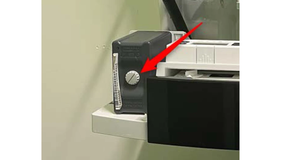
- Locate UBA3 control in the bottom left side of the boiler
- Loosen the light gray knob to allow the UBA3 to be removed. NOTE: To ensure damage is not done to components, unscrew the knob a little, then wiggle the UBA3. Repeat this process until the UBA3 is removed.
- Once the UBA3 is removed, visually inspect the 81 pin plug and the pins themselves for damage.
Result:
- If the pins are damaged on the UBA3, contact a Bosch technical support specialist.
- If the plug is damaged, replace the low voltage wiring harness. The part number is available through the Aftermarket Resource Center.
- If no damage is visible, re-seat the UBA3 control and ensure the light gray knob is tightened. Go to step 2.
Step 2. Check the plug connection
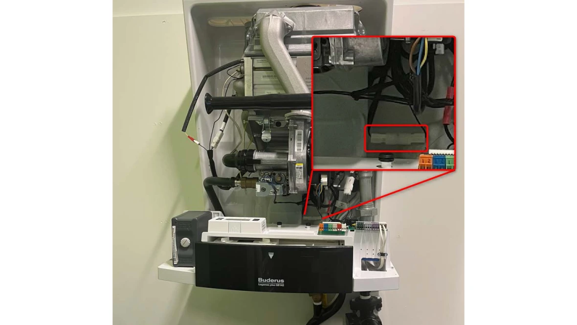
- Locate the white plug connection just below the blower fan.
- Disconnect this plug and visually inspect for any damage, loose wires or corrosion.
- Trace the wires through the harness to the UBA3 control and check for any visible damage.
Result:
- If the wires are damaged, replace the low voltage wiring harness. The part number is available through the Aftermarket Resource Center.
- If the plug is damaged, replace the low voltage wiring harness. The part number is available through the Aftermarket Resource Center.
- If there is no visible damage, all wiring connections are tight and the error is still coming up, contact the Bosch technical support specialists.
2E Error Code
2E Error Code
Tools Needed
Hand Tools
Pressure Gauge
Error Code Information
| Models | GB142/24, GB142/30, GB142/45, GB142/60 |
| Error Code | 2E |
| Error Code Meaning | Water pressure is too low (3 PSI or less) |
| Possible Causes |
Low water pressure Faulty pressure sensor |
Troubleshooting Steps
Step 1. Determine the water pressure in the system.
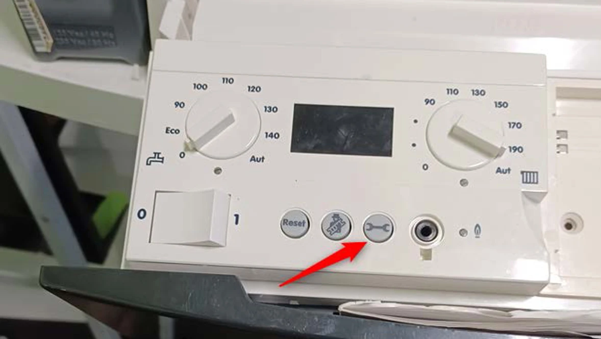
- Open the front of the control panel to reveal the buttons.
- Push the wrench button on the front of the controls to get "P" and a number. This number is water pressure in the boiler measured in PSI.
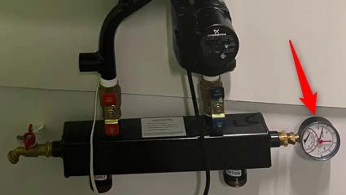
- Compare this reading with the pressure reading from a gauge located somewhere else on the boiler system. EX: There may be a pressure gauge on the low loss header.
- If there isn't a gauge installed on the system, one will need to be applied to a hose fitting on the boiler system.
Results:
- If the pressure reading on the control doesn't match the reading from the pressure gauge, you will need to determine which is correct.
- If the dial gauge is correct, go to step 2.
- If the control is correct or if the reading is the same, you will need to add water to the boiler system and check for any leaks.
Step 2. Checking the pressure sensor
- Shut off power to the boiler
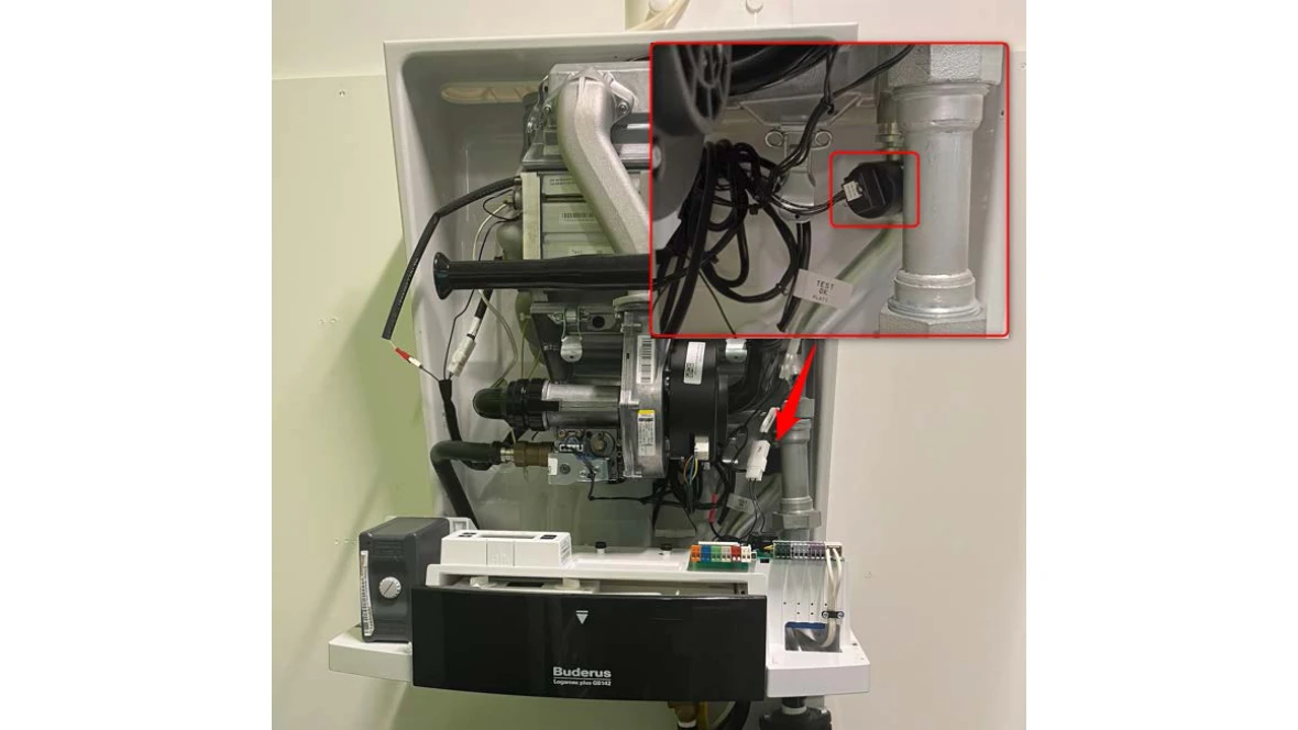
- Locate the pressure sensor on the right hand side of the boiler, just below the heat exchanger.
- Disconnect the wire from the sensor and visually inspect both the sensor and wire for any damage or corrosion.
- Locate UBA3 control in the bottom left side of the boiler
- Loosen the light gray knob to allow the UBA3 to be removed. NOTE: To ensure damage is not done to components, unscrew the knob a little, then wiggle the UBA3. Repeat this process until the UBA3 is removed.
- Once the UBA3 is removed, visually inspect the 81 pin plug and the pins themselves for damage.
- Trace the wires back from the pressure sensor to the UBA3 control and visually inspect for damage.
Result:
- If the wires are damaged, replace the low voltage wiring harness. The part number is available through the Aftermarket Resource Center.
- If the pressure sensor is damaged or corroded, replace the pressure sensor. The part number is available through the Aftermarket Resource Center.
- If there is no visible damage, it will either be the pressure sensor or the UBA3 control. Neither of these can be tested individually, so replace the pressure sensor first. If that does not resolve the issue, contact the Bosch technical support specialists.
2F Error Code
2F Error Code
Tools Needed
Digital Multi-meter
Pressure Gauge
Thermometer
Error Code Information
| Models | GB142/24, GB142/30, GB142/45, GB142/60 |
| Error Code | 2F |
| Error Code Meaning | Temp difference between supply and safety sensors too high after burner start |
| Possible Causes |
Air in heat exchanger Faulty pump for DHW Faulty boiler pump Faulty supply or safety sensor Defective wiring Faulty UBA control |
Troubleshooting Steps
Step 1. Confirm call for heat or DHW
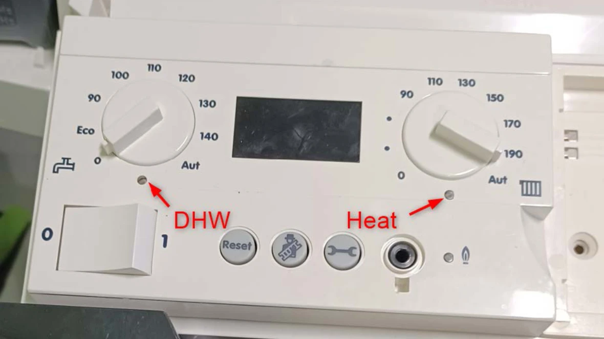
- When there is a call for hot water (heat or DHW) a green light will be lit under the set point dial of the control.
Results:
- If the DHW light is lit or if both lights are lit, follow the DHW instructions below.
- If the heat light is lit, follow the Heat instructions below.
DHW Instructions
Step 1. Determine if DHW pump is getting power.
- In the bottom right corner of the boiler is a green control board.
- Using a digital multi-meter, test for VAC across the PS plug labeled 24 and 25.
Results:
- If there is 120 VAC (+/- 10%), there isn't any water flow in the DHW loop. Go to the DHW loop instructions below.
- If there isn't 120 VAC (+/- 10%), there is a power supply issue. Go to the Power Supply instructions below.
DHW loop
- Checking the DHW loop pump.
- Note: This pump was not supplied with the boiler, so we can only suggest how to verify if the pump is faulty with the points below.
- If the pump is very hot to the touch, it could be sign that the motor is seized.
- Every pump has an amp draw that is noted on a label. This can be tested to see if it is drawing the correct amount of amps.
- Check for valves that may be shut off.
- Check for air in the loop.
Power Supply
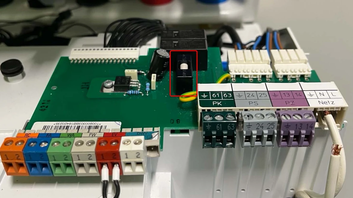
Step 1. Check the fuse
- Shut power off to the boiler.
- In the center of the green control board is the fuse in a black housing. Pull up on the housing to remove the fuse.
- Using a digital multi-meter set to standard ohms or continuity, test the fuse.
Results:
- If there is continuity or an ohm reading through the fuse, go to step 2.
- If there is no continuity or an OL reading through the fuse, there is likely a short in the wiring from the pump to the control board or a faulty pump. Inspect wiring and pump for damage or shorts replace or repair faulty component.
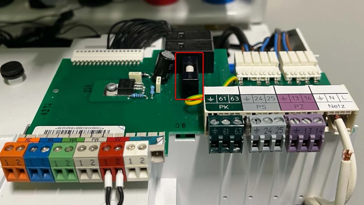
Step 2. Checking wiring
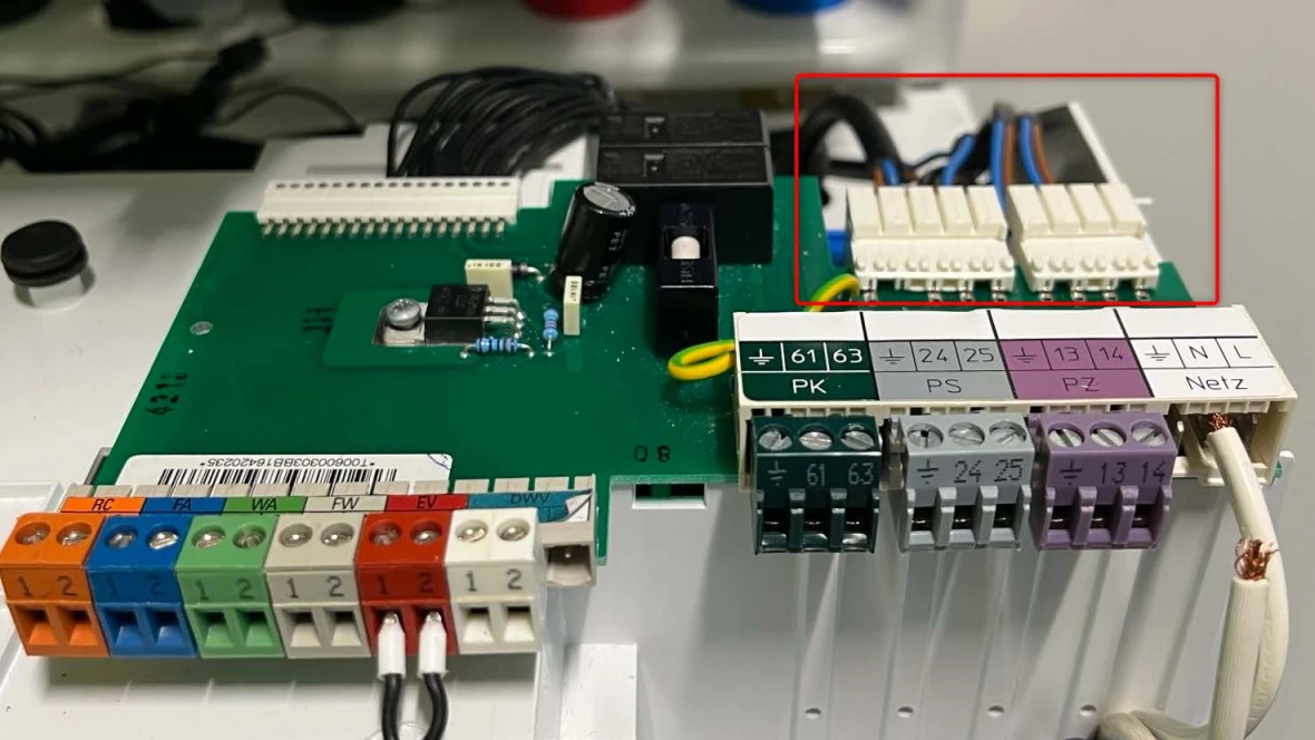
- Starting at the rear right hand side of the green control board, follow the wires to the UBA3 control (gray box component in the bottom left corner of the boiler) and check for any damage or loose wires.
Results:
- If the wires are damaged or corroded, replace the high voltage wiring harness. The part number is available through the Aftermarket Resource Center.
- If the wires are not damaged or corroded, go to step 3.
Step 3. Re-seat the UBA3 control
- Locate UBA3 control in the bottom left side of the boiler
- Loosen the light gray knob to allow the UBA3 to be removed. NOTE: To ensure damage is not done to components, unscrew the knob a little, then wiggle the UBA3. Repeat this process until the UBA3 is removed.
- Once the UBA3 is removed, visually inspect the white plastic plug for damage.
Results:
- If the white plastic plug is undamaged, reinstall the UBA3 control.
- Retest the PS 24+25 wire connections for voltage.
- If no voltage, contact the Bosch technical support specialists.
- If there is voltage, the code should have gone away and the boiler working normally.
- If the white plastic plug is damaged, replace the high voltage wiring harness.
- The part number is available through the Aftermarket Resource Center.
Heat Instructions
Step 1. Determine if pump is powered
- In the bottom right corner of the boiler is a green control board.
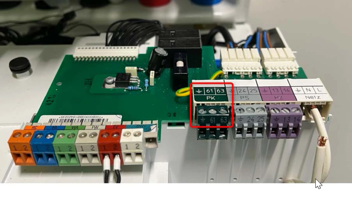
- Using a digital multi-meter, test for VAC across the PK plug labeled 61 and 63.
Results:
- If there is 120VAC (+/- 10%), and there isn't any water flow in the header loop, go to Header Loop instructions below.
- If there isn't 120VAC (+/- 10%), there is a power supply issue. Go to the Power Supply instructions below.
Header Loop
- Check the header loop pump.
- Note: While this pump was supplied with the boiler, we can only suggest how to verify if the pump is faulty with the points below.
- If the pump is very hot to the touch, it could be sign that the motor is seized.
- Every pump has an amp draw that is noted on a label. This can be tested to see if it is drawing the correct amount of amps.
- Check for valves that may be shut off.
- Check for air in the loop and the boiler.
Power Supply
Step 1. Checking wiring
- Starting at the rear right hand side of the green control board, follow the wires to the UBA3 control (gray box component in the bottom left corner of the boiler) and check for any damage or loose wires.
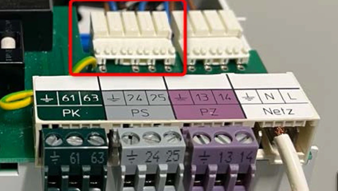
Results:
- If the wires are damaged or corroded, replace the high voltage wiring harness.
- The part number is available through the Aftermarket Resource Center.
- If the wires are not damaged or corroded, go to step 2.
Step 2. Re-seat the UBA3 control
- Locate UBA3 control in the bottom left side of the boiler
- Loosen the light gray knob to allow the UBA3 to be removed. NOTE: To ensure damage is not done to components, unscrew the knob a little, then wiggle the UBA3. Repeat this process until the UBA3 is removed.
- Once the UBA3 is removed, visually inspect the white plastic plug for damage.
Results:
- If the white plastic plug is undamaged, reinstall the UBA3 control.
- Retest the PK 61+63 wire connections for voltage.
- If no voltage, contact the Bosch technical support specialists.
- If there is voltage, the code should have gone away and the boiler working normally.
- If the white plastic plug is damaged, replace the high voltage wiring harness.
- The part number is available through the Aftermarket Resource Center.
3C, 3L Error Code
3C, 3L Error Code
Tools Needed
Digital Multi-meter
Hand Tools
Error Code Information
| Models | GB142/24, GB142/30, GB142/45, GB142/60 |
| Error Code |
3C 3L |
| Error Code Meaning | Fan signal lost during operation. |
| Possible Causes |
Faulty Fan (most common cause) Faulty UBA3 Control Faulty Low Voltage Harness Faulty High Voltage Harness |
Troubleshooting Steps
Step 1. Checking voltage to the fan
- Disconnect the front plug from the fan.
- Reset the error code if it hasn't already been reset.
- Using a digital multi-meter, measure for VAC between the brown and blue wire.
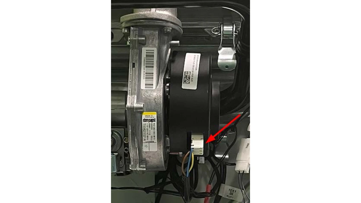
Results:
- If you have 120 VAC (+/- 10%) and the fan isn't running, replace the fan. The part number is available through the Aftermarket Resource Center.
- If you don't have 120 VAC (+/- 10%), go to step 2. Note: You will not have 120VAC on that plug if there is an error on the screen.
Step 2. Checking wiring
- Starting at the plug, follow the wires to the UBA3 control (gray box component in the bottom left corner of the boiler) and check for any damage or loose wires.
Results:
- If the wires are damaged or corroded, replace the high voltage wiring harness. The part number is available through the Aftermarket Resource Center.
- If the wires are not damaged or corroded, go to step 3.
Step 3. Re-seat the UBA3 control
- Locate UBA3 control in the bottom left side of the boiler
- Loosen the light gray knob to allow the UBA3 to be removed. NOTE: To ensure damage is not done to components, unscrew the knob a little, then wiggle the UBA3. Repeat this process until the UBA3 is removed.
- Once the UBA3 is removed, visually inspect the white plastic plug for damage.
Results:
- If the white plastic plug is undamaged, re-install the UBA3 control.
- Retest the voltage to the fan as done in step 1.
- If no voltage, contact the Bosch technical support specialists.
- If there is voltage, the code should have gone away and the boiler working normally.
- If the white plastic plug is damaged, replace the high voltage wiring harness. The part number is available through the Aftermarket Resource Center.
- Retest the voltage to the fan as done in step 1.
3P Error Code
3P Error Code
Tools Needed
Digital Multi-meter
Hand Tools
Error Code Information
| Models | GB142/24, GB142/30, GB142/45, GB142/60 |
| Error Code | 3P |
| Error Code Meaning | Fan is running too slow |
| Possible Causes |
Faulty Fan (most common cause) Faulty UBA3 Control Faulty Low Voltage Harness |
Troubleshooting Steps
Step 1. Checking voltage to the fan
- Disconnect the front plug from the fan.
- Reset the error code if it hasn't already been reset.
- Using a digital multi-meter, measure for VAC between the brown and blue wire.
Results:
- If they have 120 VAC (+/- 10%), remove the 4 wire plug from the bottom of the fan and reset the unit.
- If the fan still runs at a low speed, replace the fan. The part number is available through the Aftermarket Resource Center.
- If the fan ramps up to high speed....
Checking wiring- Starting at the bottom fan plug, follow the wires to the UBA3 control (gray box component in the bottom left corner of the boiler) and check for any damage or loose wires.
Results:
- If the wires are damaged or corroded, replace the low voltage wiring harness. The part number is available through the Aftermarket Resource Center.
- If the wires are not damaged or corroded, go to the next step.
- If they don't have 120 VAC (+/- 10%), go to step 2.
Step 2 Checking wiring
- Starting at the plug, follow the wires to the UBA3 control (gray box component in the bottom left corner of the boiler) and check for any damage or loose wires.
Results:
- If the wires are damaged or corroded, replace the high voltage wiring harness. The part number is available through the Aftermarket Resource Center.
- If the wires are not damaged or corroded, go to step 3.
Step 3. Re-seat the UBA3 control
- Locate UBA3 control in the bottom left side of the boiler
- Loosen the light gray knob to allow the UBA3 to be removed. NOTE: To ensure damage is not done to components, unscrew the knob a little, then wiggle the UBA3. Repeat this process until the UBA3 is removed.
- Once the UBA3 is removed, visually inspect the white plastic plug for damage.
Results:
- If the white plastic plug is undamaged, re-install the UBA3 control.
- Retest the voltage to the fan as done in step 1.
- If no voltage, contact the Bosch technical support specialists.
- If there is voltage, the code should have gone away and the boiler working normally.
4A Error Code
4A Error Code
Tools Needed
Digital Multi-meter
Hand Tools
Thermometer
Error Code Information
| Models | GB142/24, GB142/30, GB142/45, GB142/60 |
| Error Code | 4A |
| Error Code Meaning | Supply sensor above 220 °F |
| Possible Causes |
Air in the heat exchanger Failed pump Bad sensor |
Troubleshooting Steps
Step 1. Verify temperature of the boiler block
- Using a thermometer, measure the temperature of the heat exchanger near the supply temperature sensor.
- Pull apart the disconnect for the sensor and using a digital multi-meter, measure the ohms of the sensor side of the disconnect.
- Use the chart in the manual for the 10k sensor to compare the ohm reading with the temperature reading of the heat exchanger near the sensor.
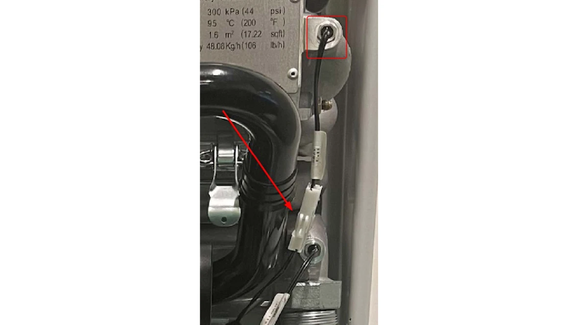
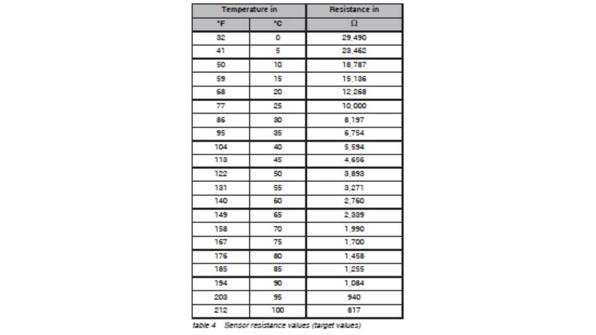
Results:
- If the temperature reading matches the ohm reading of the sensor, go to step 2.
- If the temperature reading does not match the ohm reading of the sensor, the sensor is bad.
- The part number is available through the Aftermarket Resource Center.
Step 2.
- Confirm call for heat or DHW
- When there is a call for hot water (heat or DHW) a green light will be lit under the set point dial of the control.
DHW Instructions
Step 1. Determine if DHW pump is getting power.
- In the bottom right corner of the boiler is a green control board.
- Using a digital multi-meter, test for VAC across the PS plug labeled 24 and 25.
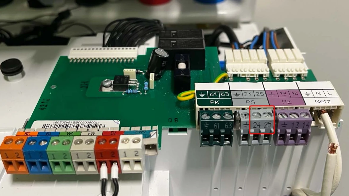
Results:
- If there is 120 VAC (+/- 10%), there isn't any water flow in the DHW loop. Go to the DHW loop instructions below.
- If there isn't 120 VAC (+/- 10%), there is a power supply issue. Go to the Power Supply instructions below.
DHW loop
Checking the DHW loop pump.
Note: This pump was not supplied with the boiler, so we can only suggest how to verify if the pump is faulty with the points below.
- If the pump is very hot to the touch, it could be sign that the motor is seized.
- Every pump has an amp draw that is noted on a label. This can be tested to see if it is drawing the correct amount of amps.
- Check for valves that may be shut off.
- Check for air in the loop.
Power Supply
Step 1. Check the fuse
- Shut power off to the boiler.
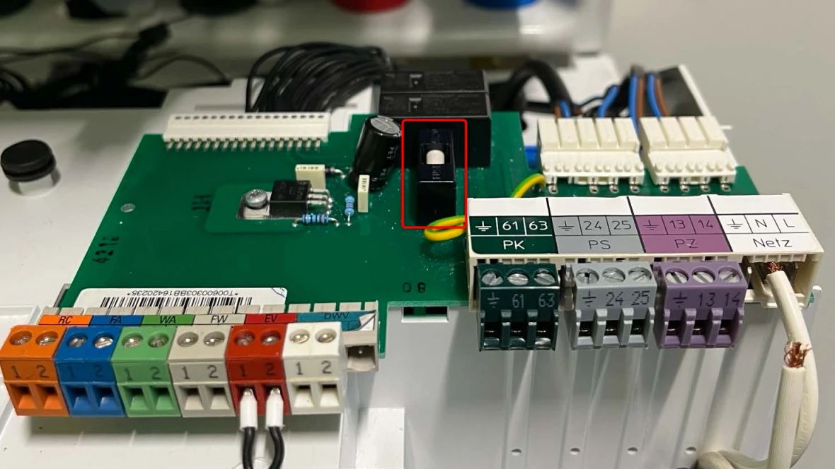
- In the center of the green control board is the fuse in a black housing. Pull up on the housing to remove the fuse.
- Using a digital multi-meter set to standard ohms or continuity, test the fuse.
Results:
- If there is continuity or an ohm reading through the fuse, go to step 2.
- If there is no continuity or an OL reading through the fuse, there is likely a short in the wiring from the pump to the control board or a faulty pump. Inspect wiring and pump for damage or shorts replace or repair faulty component.
Step 2. Checking wiring
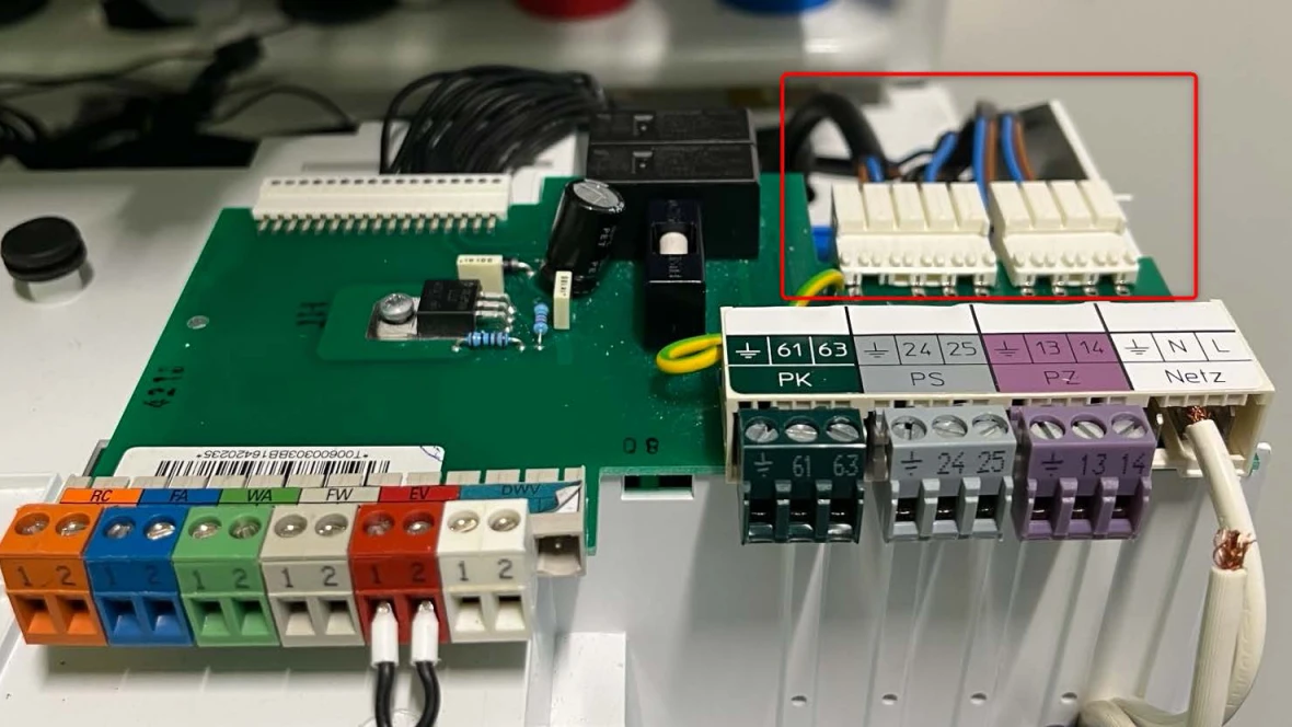
- Starting at the rear right hand side of the green control board, follow the wires to the UBA3 control (gray box component in the bottom left corner of the boiler) and check for any damage or loose wires.
Results:
- If the wires are damaged or corroded, replace the high voltage wiring harness.
- The part number is available through the Aftermarket Resource Center.
- If the wires are not damaged or corroded, go to step 3.
Step 3. Re-seat the UBA3 control
- Locate UBA3 control in the bottom left side of the boiler
- Loosen the light gray knob to allow the UBA3 to be removed. NOTE: To ensure damage is not done to components, unscrew the knob a little, then wiggle the UBA3. Repeat this process until the UBA3 is removed.
- Once the UBA3 is removed, visually inspect the white plastic plug for damage.
Results:
- If the white plastic plug is undamaged, reinstall the UBA3 control.
- Retest the PS 24+25 wire connections for voltage.
- If no voltage, contact the Bosch technical support specialists.
- If there is voltage, the code should have gone away and the boiler working normally.
- If the white plastic plug is damaged, replace the high voltage wiring harness.
- The part number is available through the Aftermarket Resource Center.
Heat Instructions
Step 1. Determine if pump is powered
- In the bottom right corner of the boiler is a green control board.
- Using a digital multi-meter, test for VAC across the PK Plug labeled 61 and 63.
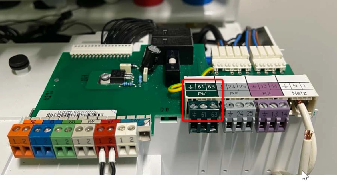
Results:
- If there is 120VAC (+/- 10%), and there isn't any water flow in the header loop, go to Header Loop instructions below.
- If there isn't 120VAC (+/- 10%), there is a power supply issue. Go to the Power Supply instructions below.
Header Loop
- Check the header loop pump.
- Note: While this pump was supplied with the boiler, we can only suggest how to verify if the pump is faulty with the points below.
- If the pump is very hot to the touch, it could be sign that the motor is seized.
- Every pump has an amp draw that is noted on a label. This can be tested to see if it is drawing the correct amount of amps.
- Check for valves that may be shut off.
- Check for air in the loop and the boiler.
Power Supply
Step 1. Checking wiring
- Starting at the rear right hand side of the green control board, follow the wires to the UBA3 control (gray box component in the bottom left corner of the boiler) and check for any damage or loose wires.
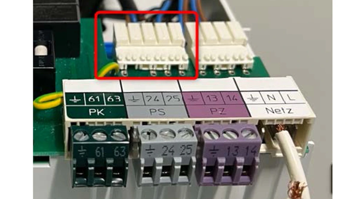
Results:
- If the wires are damaged or corroded, replace the high voltage wiring harness.
- The part number is available through the Aftermarket Resource Center.
- If the wires are not damaged or corroded, go to step 2.
Step 2. Re-seat the UBA3 control
- Locate UBA3 control in the bottom left side of the boiler
- Loosen the light gray knob to allow the UBA3 to be removed.
- NOTE: To ensure damage is not done to components, unscrew the knob a little, then wiggle the UBA3. Repeat this process until the UBA3 is removed.
- Once the UBA3 is removed, visually inspect the white plastic plug for damage.
Results:
- If the white plastic plug is undamaged, reinstall the UBA3 control.
- Retest the PK 61+63 wire connections for voltage.
- If no voltage, contact the Bosch technical support specialists.
- If there is voltage, the code should have gone away and the boiler working normally.
- If the white plastic plug is damaged, replace the high voltage wiring harness.
- The part number is available through the Aftermarket Resource Center.
6A Error Code
6A Error Code
Tools Needed
Digital Multi-meter
Combustion Analyzer
Gas manometer
Hand Tools
Error Code Information
| Models | GB142/24, GB142/30, GB142/45, GB142/60 |
| Error Code | 6A |
| Error Code Meaning |
No flame after 4 consecutive tries to fire |
| Possible Causes |
Failed ignitor Worn flame rod Blocked venting Dirty boiler Broken venturi Gas supply issues Condensate not draining |
Troubleshooting Steps
Step 1. Check inlet gas pressure
- Shut off power to the boiler.
- Using a manometer, measure the inlet gas pressure on the left port of the gas valve. Shut the gas supply off, turn the screw counterclockwise 2 full turns, slide the manometer hose over the port, and then re open gas supply.
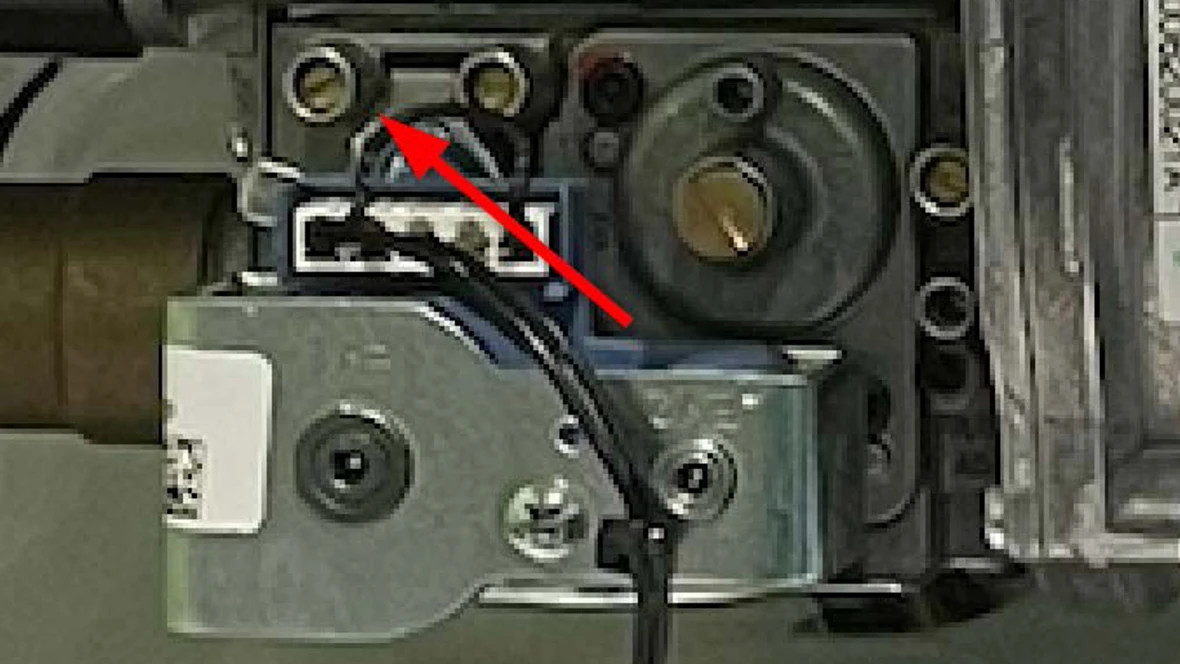
Results:
- If the gas pressure measures between the ranges below, go to step 2.
- Natural Gas (NG) = 3.5" - 10.5" WC
- Liquid Propane (LP) = 8" - 13" WC
- If the gas pressure does not fall within the ranges noted above, there is a gas supply issue. A trained professional will need to identify the issue within the gas supply system.
Step 2. Check the igniter
- Reset the unit and look in the window on the right hand side of the heat exchanger for an orange glow in the sight glass.
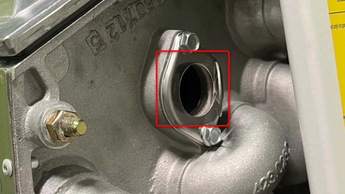
Results:
- If there is an orange glow, the igniter is good. Contact the Bosch technical support specialists.
- If there isn't an orange glow...
- If there isn't an orange glow, the resistance of the igniter will need to be measured.
- On the left side of the heat exchanger, there are two white wires that lead to the igniter.
Pull apart the disconnect for these wires.
- On the left side of the heat exchanger, there are two white wires that lead to the igniter.
- Using digital multi-meter set to ohms, measure across the igniter side of the disconnect.
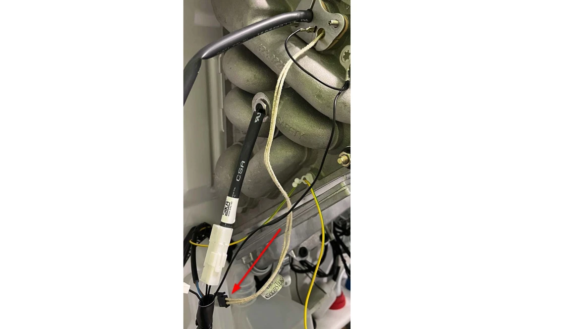
Results:
- If the ohm reading is 50-300 ohms, the igniter is good. Contact the Bosch technical support specialists.
- If the ohm reading is outside of 50-300 ohms, the igniter is bad and should be replaced.
- The part number is available through the Aftermarket Resource Center.
6C Error Code
6C Error Code
Tools Needed
Digital Multi-meter
Combustion Analyzer
Gas manometer
Hand Tools
Error Code Information
| Models | GB142/24, GB142/30, GB142/45, GB142/60 |
| Error Code | 6C |
| Error Code Meaning | Flame signal before burner start |
| Possible Causes |
Faulty flame rod/ ionization rod Faulty gas valve Faulty control |
Troubleshooting Steps
Step 1. Check Condition of the flame rod
- Locate the flame rod on the left side of the boiler block it will be next to the hot surface igniter.
- Remove the flame rod from the boiler block and visually inspect it.
Results:
- If the flame rod is pitted or corroded or worn to a point it should be replaced. The part number is available through the Aftermarket Resource Center.
- If the flame rod is in good condition contact the Bosch technical support specialists.
6L Error Code
6L Error Code
Tools Needed
Digital Multi-meter
Combustion Analyzer
Gas manometer
Hand Tools
Error Code Information
| Models | GB142/24, GB142/30, GB142/45, GB142/60 |
| Error Code | 6L |
| Error Code Meaning | Burner failure during operation |
| Possible Causes |
Faulty flame rod/ Ionization Rod Air flow restriction Gas Pressure Issue Faulty Control |
Troubleshooting Steps
Step 1. Check inlet gas pressure
- Shut off power to the boiler.
- Using a manometer, measure the static inlet gas pressure on the left port of the gas valve. Shut the gas supply off, turn the screw counterclockwise 2 full turns, slide the manometer hose over the port, and then re open gas supply.
- Turn power back on to the boiler and give a call for heat or hot water so the boiler tries to fire.
- While the boiler is trying to fire, get the dynamic gas pressure.
Results:
- If the static gas pressure measures between the ranges below and the difference between static and dynamic pressure is under 2" WC, go to the step 2.
- Natural Gas (NG) = 3.5" - 10.5" WC
- Liquid Propane (LP) = 8" - 13" WC
- If the static pressure is not within the range, or the difference between the static and dynamic pressure is more than 2" WC, contact the Bosch technical support specialists.
Step 2. Visual inspection of the flame rod.
- Shut off power to the boiler.
- On the top left side of the heat exchanger is the plate that has the flame rod and hot surface igniter on it. Remove the two bolts to pull the plate out so the flame rod can be visually inspected.
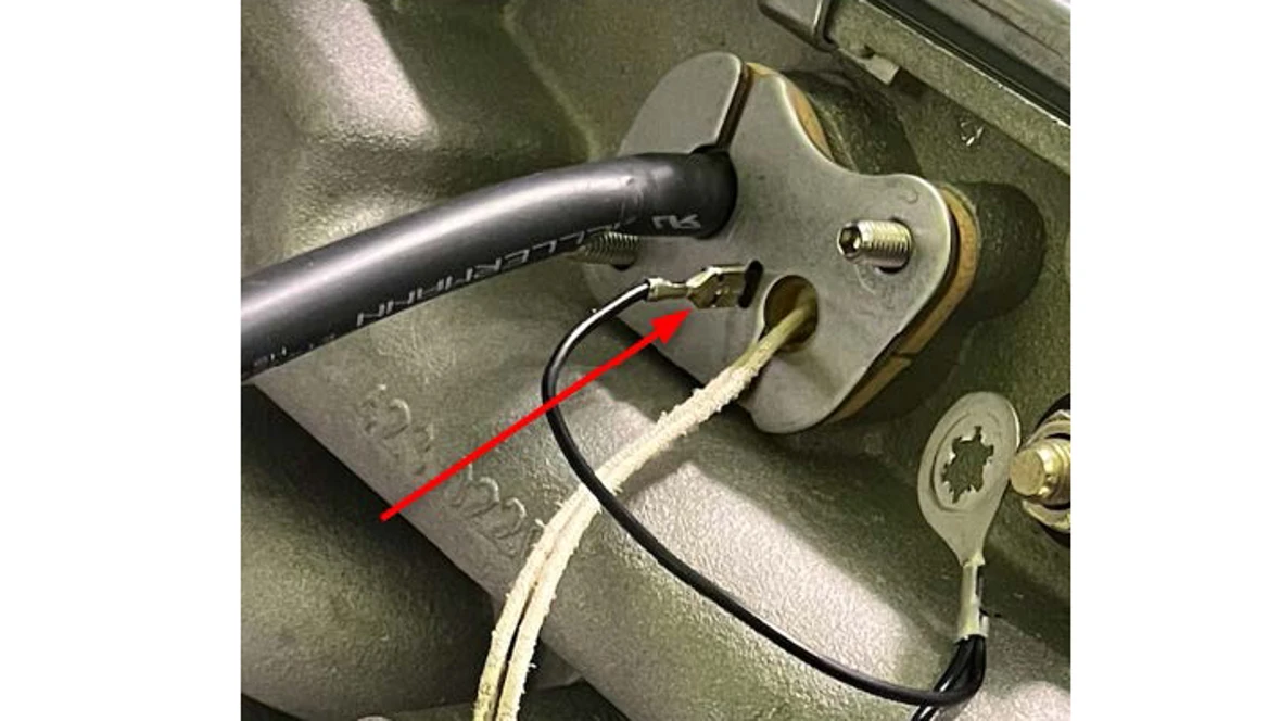
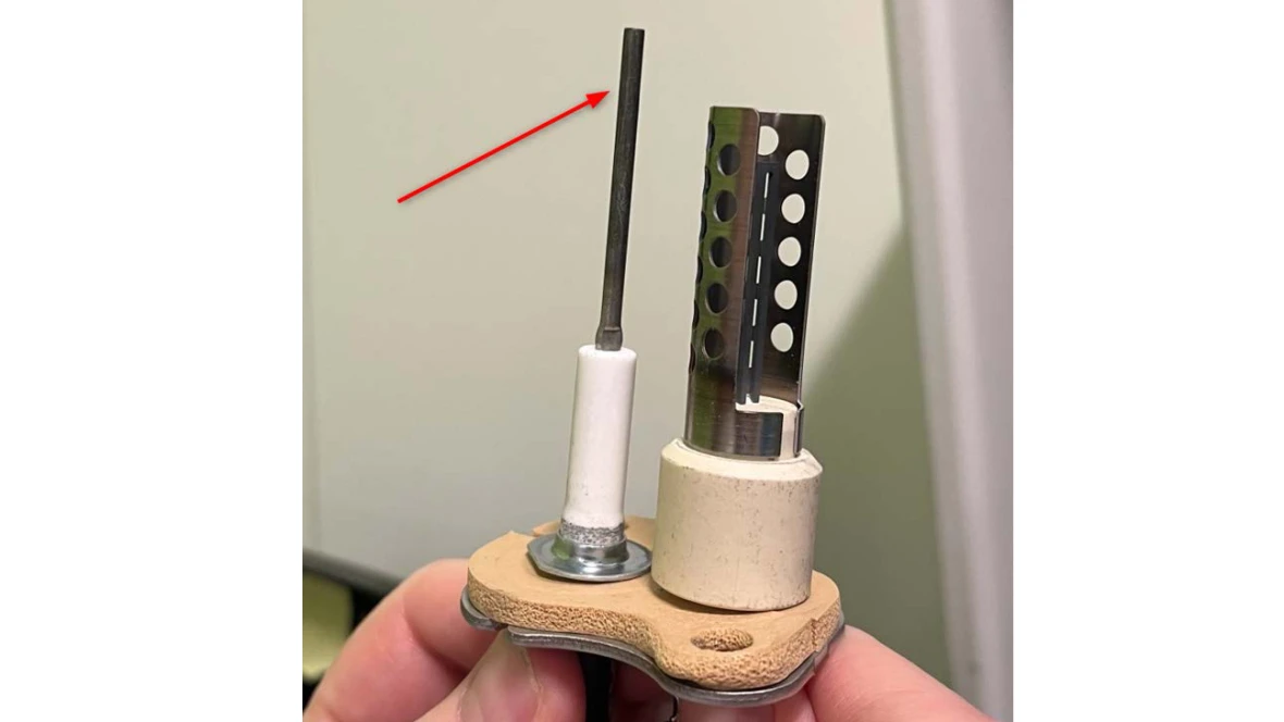
Results:
- If the flame rod is corroded, pitted, or pointy, it's a bad flame rod and should be replaced. The part number is available through the Aftermarket Resource Center.
- If the flame rod is in good condition contact the Bosch technical support specialists.
9L Error Code
9L Error Code
Tools Needed
Digital Multi-meter
Hand Tools
Error Code Information
| Models | GB142/24, GB142/30, GB142/45, GB142/60 |
| Error Code | 9L |
| Error Code Meaning | Gas valve disconnected |
| Possible Causes |
Gas valve unplugged Gas valve faulty Faulty wiring harness Faulty control |
Troubleshooting Steps
Step 1. Visually inspect the plug connection to the gas valve.
- Shut off power to the boiler.
- In the center of the boiler is the gas valve. Make sure the plug connection is tight into the gas valve.
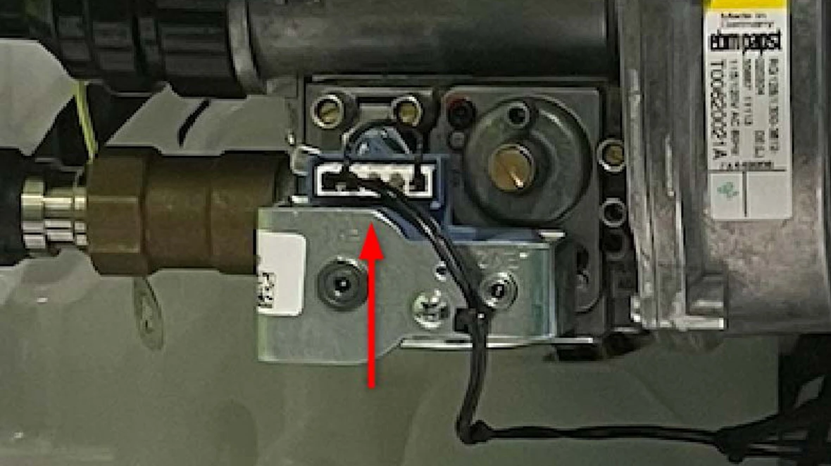
Results:
- If the plug was loose and is now tight, reset the boiler.
- If the code does not come up again, the issue has been resolved.
- If the code does come up again, go to step 2.
- If the plug is not loose, go to step 2.
Step 2. Checking gas valve coil resistance.
- Disconnect the plug connected to the gas valve.
- There will be 3 pins visible on the gas valve.
- Using a digital multi-meter set to ohms, take the following measurements:
- One probe on the left pin (1), other probe on the middle pin (2). Note the results.
- One probe on the middle pin (2), other probe on the right pin (3). Note the results.
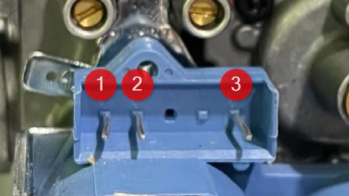
Results:
- If the results fall within the specs below, go to step 3.
- Left (1) to Middle (2) = 75 ohms (+/- 10%)
- Right (3) to Middle (2) = 185 ohms (+/- 10%)
- If the results do not fall within the specs above, replace the gas valve.
Step 3. Visually inspect the wiring harness.
- Follow the wires from the gas valve plug back to the UBA3 control and inspect for damaged wires, connectors, or corrosion.
Results:
- If the harness shows damage to the wire, connectors or corrosion, replace the low voltage wiring harness. The part number is available through the Aftermarket Resource Center.
- If no damage is found, go to step 4.
Step 4. Re-seat the UBA3 control
- Locate UBA3 control in the bottom left side of the boiler
- Loosen the light gray knob to allow the UBA3 to be removed. NOTE: To ensure damage is not done to components, unscrew the knob a little, then wiggle the UBA3. Repeat this process until the UBA3 is removed.
- Once the UBA3 is removed, visually inspect the grey plastic plug for damage.
Results:
- If the gray plastic plug is undamaged, re-install the UBA3 control, turn power back on and see if the error goes away.
- If the error goes away, the issue is resolved.
- If the error does not go away, try re-seating a second time. If it still doesn't go away, replace the low voltage wiring harness. The part number is available through the Aftermarket Resource Center.
- NOTE: There is a VERY slight possibility it could be a bad UBA3 control. In most cases it will be an issue with the low voltage wiring harness. If the low voltage harness was already replaced the harness and the error still occurs, contact the Bosch technical support specialists.
=H Code
=H Code
Tools Needed
N/A
Error Code Information
| Models | GB142/24, GB142/30, GB142/45, GB142/60 |
| Error Code | =H |
| Error Code Meaning | This is not an error code. Its in indicator that the boiler is in hot water mode. |
| Possible Causes | N/A |
CA Error Code
CA Error Code
Tools Needed
Digital Multi-meter
Hand Tools
Thermometer
Error Code Information
| Models | GB142/24, GB142/30, GB142/45, GB142/60 |
| Error Code | CA |
| Error Code Meaning | Return sensor reading greater than 220 degrees F |
| Possible Causes |
Faulty Sensor Faulty wiring harness or plug No circulation in boiler system Faulty UBA3 Control (rare) |
Troubleshooting Steps
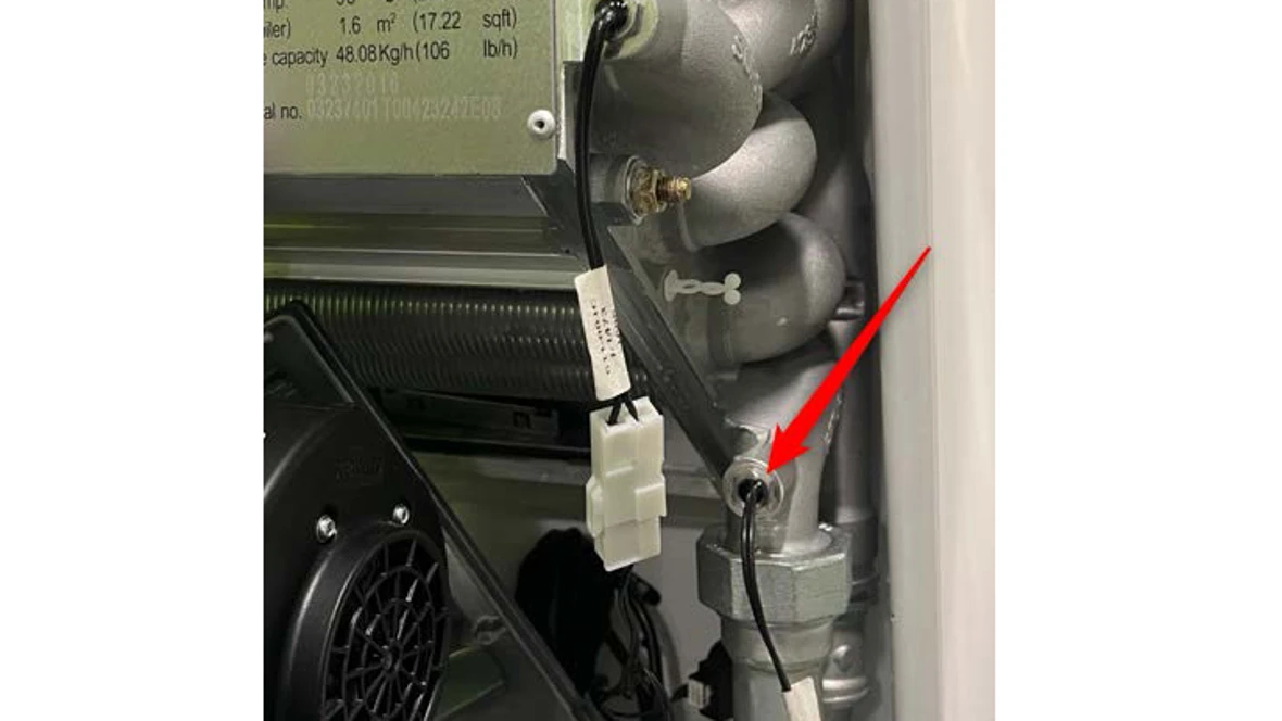
Step 1. Ohm out the return sensor.
- Locate the return sensor on the lower right side of the boiler.
- Follow the black wires from the sensor to the white plastic plug and disconnect the wires.
- Using a digital multi-meter, ohm out the sensor side of the disconnect.
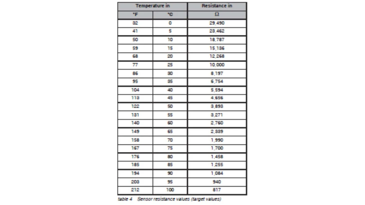
- Compare the ohm reading to the temperature reading of the pipe using the chart in the installation manual.
Results:
- If the ohm reading matches the temperature reading in the chart, the sensor is good, go to step 2.
- If the ohm reading doesn't match the temperature reading in the chart, the sensor is bad.
- Replace the sensor. The part number is available through the Aftermarket Resource Center.
Step 2. Confirm call for heat or DHW
- When there is a call for hot water (heat or DHW) a green light will be lit under the set point dial of the control.
Results:
- If the DHW light is lit or if both lights are lit, follow the DHW instructions below.
- If the heat light is lit, follow the Heat instructions below.
DHW Instructions
Step 1. Determine if DHW pump is getting power.
- In the bottom right corner of the boiler is a green control board.
- Using a digital multi-meter, test for VAC across the PS terminals labeled 24 and 25.
Results:
- If there is 120 VAC (+/- 10%), there isn't any water flow in the DHW loop. Go to the DHW loop instructions below.
- If there isn't 120 VAC (+/- 10%), there is a power supply issue. Go to the Power Supply instructions below.
DHW loop
- Checking the DHW loop pump.
- Note: This pump was not supplied with the boiler, so we can only suggest how to verify if the pump is faulty with the points below.
- If the pump is very hot to the touch, it could be sign that the motor is seized.
- Every pump has an amp draw that is noted on a label. This can be tested to see if it drawing the correct amount of amps.
- Check for valves that may be shut off.
- Check for air in the loop.
Power Supply
Step 1. Check the fuse
- Shut power off to the boiler.
- In the center of the green control board is the fuse in a black housing. Pull up on the housing to remove the fuse.
- Using a digital multi-meter set to standard ohms or continuity, test the fuse.
Results:
- If there is continuity or an ohm reading through the fuse, go to step 2.
- If there is no continuity or an OL reading through the fuse, there is likely a short in the wiring from the pump to the control board or a faulty pump. Inspect wiring and pump for damage or shorts replace or repair faulty component.
Step 2. Checking wiring
- Starting at the rear right hand side of the green control board, follow the wires to the UBA3 control (gray box component in the bottom left corner of the boiler) and check for any damage or loose wires.
Results:
- If the wires are damaged or corroded, replace the high voltage wiring harness.
- The part number is available through the Aftermarket Resource Center.
- If the wires are not damaged or corroded, go to step 3.
Step 3. Re-seat the UBA3 control
- Locate UBA3 control in the bottom left side of the boiler
- Loosen the light gray knob to allow the UBA3 to be removed.
- NOTE: To ensure damage is not done to components, unscrew the knob a little, then wiggle the UBA3. Repeat this process until the UBA3 is removed.
- Once the UBA3 is removed, visually inspect the white plastic plug for damage.
Results:
- If the white plastic plug is undamaged, reinstall the UBA3 control.
- Retest the PS 24+25 wire connections for voltage.
- If no voltage contact the Bosch technical support specialists.
- If there is voltage, the code should have gone away and the boiler working normally.
- If the white plastic plug is damaged, replace the high voltage wiring harness.
- The part number is available through the Aftermarket Resource Center.
Heat Instructions
Step 1. Determine if pump is powered
- In the bottom right corner of the boiler is a green control board.
- Using a digital multi-meter, test for VAC across the PK terminals labeled 61 and 63.
Results:
- If there is 120VAC (+/- 10%), and there isn't any water flow in the header loop, go to Header Loop instructions below.
- If there isn't 120VAC (+/- 10%), there is a power supply issue. Go to the Power Supply instructions below.
Header Loop
- Check the header loop pump.
- Note: While this pump was supplied with the boiler, we can only suggest how to verify if the pump is faulty with the points below.
- If the pump is very hot to the touch, it could be sign that the motor is seized.
- Every pump has an amp draw that is noted on a label. This can be tested to see if it drawing the correct amount of amps.
- Check for valves that may be shut off.
- Check for air in the loop and the boiler.
Power Supply
Step 1. Checking wiring
- Starting at the rear right hand side of the green control board, follow the wires to the UBA3 control (gray box component in the bottom left corner of the boiler) and check for any damage or loose wires.
Results:
- If the wires are damaged or corroded, replace the high voltage wiring harness.
- The part number is available through the Aftermarket Resource Center.
- If the wires are not damaged or corroded, go to step 2.
Step 2. Re-seat the UBA3 control
- Locate UBA3 control in the bottom left side of the boiler
- Loosen the light gray knob to allow the UBA3 to be removed.
- NOTE: To ensure damage is not done to components, unscrew the knob a little, then wiggle the UBA3. Repeat this process until the UBA3 is removed.
- Once the UBA3 is removed, visually inspect the white plastic plug for damage
Results:
- If the white plastic plug is undamaged, reinstall the UBA3 control.
- Retest the PK 61+63 wire connections for voltage.
- If no voltage, contact the Bosch technical support specialists.
- If there is voltage, the code should have gone away and the boiler working normally.
- If the white plastic plug is damaged, replace the high voltage wiring harness.
- The part number is available through the Aftermarket Resource Center.
CO Error Code
CO Error Code
Tools Needed
Hand Tools
Error Code Information
| Models | GB142/24, GB142/30, GB142/45, GB142/60 |
| Error Code | CO |
| Error Code Meaning | No communication between the UBA3 control and the pressure sensor. |
| Possible Causes |
Unplugged sensor Bad sensor Bad UBA Faulty wiring |
Troubleshooting Steps
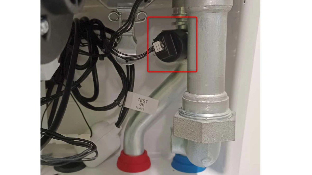
Step 1. Inspect the wire between the pressure sensor and the UBA3 control.
- The pressure sensor is a round black plastic piece attached to the supply pipe on the right side of the boiler. Follow and examine the wire from the sensor to where the harness plugs into the UBA3 control.
Results:
- If the wires are damaged, replace the low voltage wiring harness. The part number is available through the Aftermarket Resource Center.
- If the pressure sensor is damaged or corroded, replace the pressure sensor. The part number is available through the Aftermarket Resource Center.
- If there is no visible damage, it will either be the pressure sensor or the UBA3 control. Neither of these can be tested individually, so replace the pressure sensor first. If that does not resolve the issue, contact the Bosch technical support specialists.
CU / CY Error Code
CU / CY Error Code
Tools Needed
Digital Multi-meter
Hand Tools
Error Code Information
| Models | GB142/24, GB142/30, GB142/45, GB142/60 |
| Error Code | CU / CY |
| Error Code Meaning | Return sensor shorted |
| Possible Causes |
Faulty sensor Faulty low voltage wiring harness Faulty UBA3 control |
Troubleshooting Steps
Step 1. Ohm the return sensor.
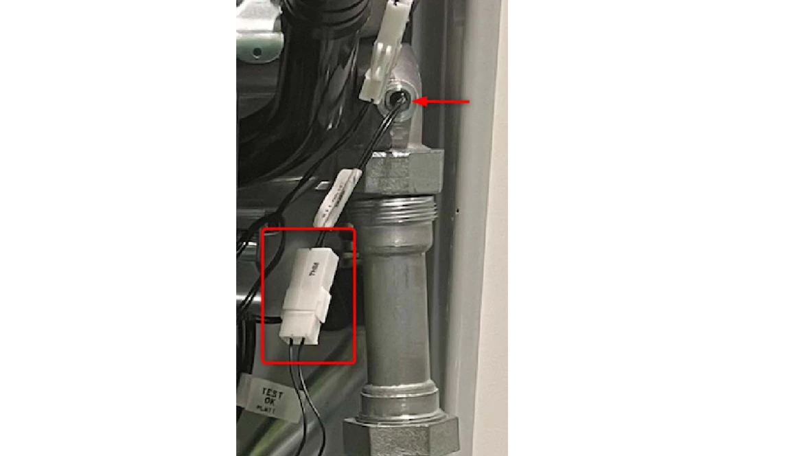
- The return sensor is screwed on to the return pipe on the right hand side of the boiler. The sensor has two black wires coming out of it that lead to a white disconnect.
- Pull apart the white disconnect.
- Using a digital multi-meter set to K ohms, place the probes of the multi-meter on the sensor side of the disconnect.
Results:
- If the sensor reads 0 or OL (open), the sensor is faulty and should be replaced. The part number is available through the Aftermarket Resource Center.
- If the sensor reads in K ohms, go to step 2.
Step 2. Measure the resistance of the sensor and wires behind the UBA3 control.
- Locate UBA3 control in the bottom left side of the boiler
- Loosen the light gray knob to allow the UBA3 to be removed. NOTE: To ensure damage is not done to components, unscrew the knob a little, then wiggle the UBA3. Repeat this process until the UBA3 is removed.
- Once the UBA3 is removed, you will see a black plug on the left hand side with 81 pins in three rows.
- On the left hand row of pins, count down from the top to pins 11 and 12.
- Using a digital multi-meter set to K ohms, place the probes of the meter on pins 11 and 12.
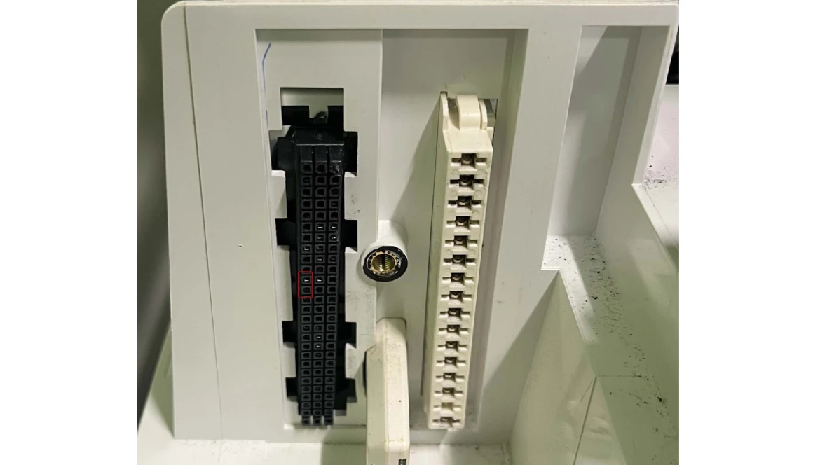
Results:
- If the sensor reads 0 or OL (open), the low voltage harness is faulty and should be replaced.
- The part number is available through the Aftermarket Resource Center.
- If the sensor reads in K ohms, go to step 3.
Step 3. Re-seat the UBA3 control
- Put the UBA3 control back into place. Ensure there is firm pressure on the UBA3 while screwing in the grey knob to ensure a tight fit.
- Turn power back on and see if the error goes away.
Results:
- If the error goes away, the issue is resolved.
- If the error does not go away, try re-seating a second time. If it still doesn't go away, replace the low voltage wiring harness. The part number is available through the Aftermarket Resource Center.
- NOTE: There is a VERY slight possibility it could be a bad UBA3 control. In most cases it will be an issue with the low voltage wiring harness. If the low voltage wiring harness has already been replaced and the error is present, contact the Bosch technical support specialists.
H7 Error Code
H7 Error Code
Tools Needed
Independent Pressure Gauge
(Like a dial pressure gauge)
Hand Tools
Error Code Information
| Models | GB142/24, GB142/30, GB142/45, GB142/60 |
| Error Code | H7 |
| Error Code Meaning | System water pressure below 14 psi. This more of a status code than an error code. This won't prevent the boiler from operating. |
| Possible Causes |
Low water pressure Faulty pressure sensor |
Troubleshooting Steps
Step 1. Verify system pressure.
- Use the independent pressure gauge to see what the system pressure is and compare it with what the control is showing.
- To see what the pressure is on the control, push the wrench button.
- The control will show a "P" and then a number. The number is the pressure reading.
Results:
- If the readings from the independent gauge and the control are more than 5psi different, you would need to determine which is the more accurate reading.
- If the independent gauge is believed to be correct, replace the pressure sensor. The part number is available through the Aftermarket Resource Center.
- If the readings are not more than 5psi different, go to step 2.
Step 2. Add water to the boiler system
- Depending on the configuration of the boiler system, there may be an auto-fill or fast fill valve, a manual fill valve or need to pump water into the system manually. You will need to find the best way water can be added to the system for that location.
Results:
- If the code goes away after water has been added to the boiler system, the issue has been resolved.
-H Code
-H Code
Tools Needed
N/A
Error Code Information
| Models | GB142/24, GB142/30, GB142/45, GB142/60 |
| Error Code | -H |
| Error Code Meaning | This is not an error code. Its in indicator that the boiler is in heating mode. |
| Possible Causes | N/A |
OA Error Code
OA Error Code
Tools Needed
Hand Tools
Jumper wire - This is a short piece of wire with clips or stripped sections at either end.
Error Code Information
| Models | GB142/24, GB142/30, GB142/45, GB142/60 |
| Error Code | OA |
| Error Code Meaning | Too many calls for heat in a short time, burner will start after 10 min. |
| Possible Causes |
End switch is "chattering" Faulty UBA3 control |
Troubleshooting Steps
Step 1. Jumper the TT connection on the boiler.
- The TT connection can be in one of two places:
- The green "WA" connection on the circuit board inside the cabinet towards the right.
- The red connection on the back of the AM10 control.
- Which ever connection has thermostat wires connected is where they will need to remove those wires and insert the jumper wire.
- Once the connection is jumpered, reset power to the unit.
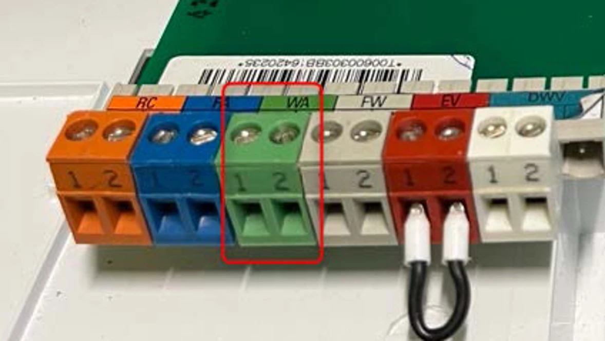
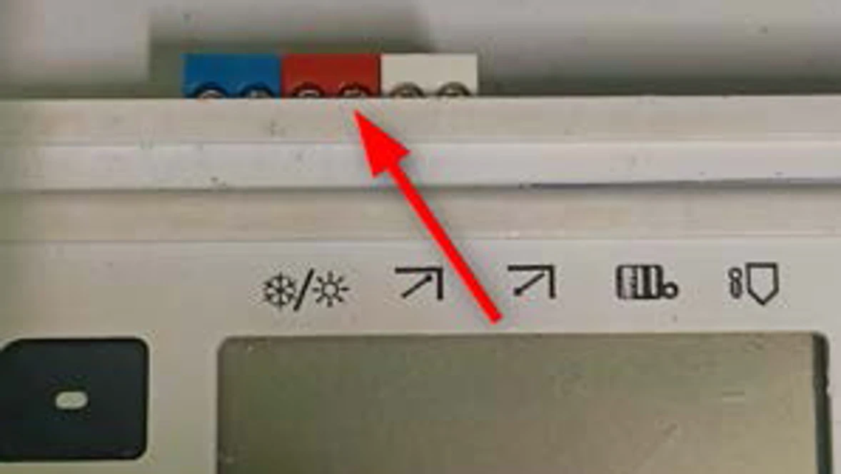
Results:
- If the unit runs without the error, you have an issue with the thermostat circuit. You will need to diagnose that issue.
- If the error comes back, go to step 2.
Step 2. Compare the boiler set point with actual boiler temperature
- There are two ways this can be done depending on whether the call for heat comes in through the AM10 or the WA terminal (whichever terminal has the thermostat wires)
With an AM10
- On the AM10 control, press the "Mode" button once until the hash mark is right below the radiator icon. This will display the boilers target temperature.
- Compare the target temperature with the temperature that is displayed on the other screen (BC10 control)
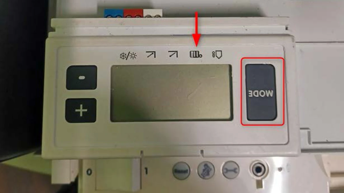
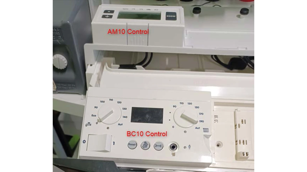
Results:
- If the actual boiler temperature is at or above the set temperature, the boiler is at limit and there isn't a problem to fix with the boiler. The issue could be in the zones because the heat is not transferring from the boiler to the zones. You would need to find the issue in the zones of the boiler system. You can raise the set temperature to potentially stop the error code from happening.
- If the actual boiler temperature is below the set temperature, contact the Bosch technical support specialists.
Without an AM10
- Compare the set point on the dial of the BC10 control with the temperature on the display.
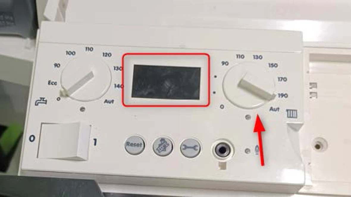
Results:
- If the actual boiler temperature is at or above the set temperature, the boiler is at limit and there isn't a problem to fix with the boiler. The issue could be in the zones because the heat is not transferring from the boiler to the zones. You would need to find the issue in the zones of the boiler system. You can raise the set temperature to potentially stop the error code from happening.
- If the actual boiler temperature is below the set temperature, contact the Bosch technical support specialists.
OH Error Code
OH Error Code
Tools Needed
Hand Tools
Jumper wire - This is a short piece of wire with clips or stripped sections at either end.
Error Code Information
| Models | GB142/24, GB142/30, GB142/45, GB142/60 |
| Error Code | OH |
| Error Code Meaning | The boiler is in standby / no heat request |
| Possible Causes |
Boiler is in warm weather shut down Faulty thermostat Faulty thermostat wire Faulty end switch |
Troubleshooting Steps
Step 1.Check warm weather shut down temperature.
- On the AM10 is a Mode button. Push this 4 times and it will display the warm weather shut down temperature setting. The black cursor will move to the snow flake/sun position and display the temp setting.
- Note this temperature setting.
- Hit the Mode button once, the cursor will move to the house with a thermometer position.
- Note this temperature.
- Get a reading of what the actual outside air temperature is.
- Note this temperature.

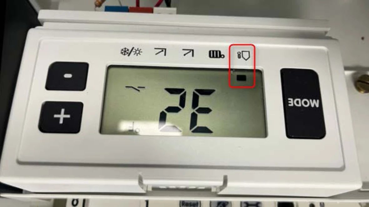
Results:
- If the actual outside air temp and the AM10 reading of the air temperature (house & thermometer icon) are not the same (slight variation is OK), the outdoor temperature sensor needs to be replaced. The part number is available through the Aftermarket Resource Center.
- If the warm weather shut down setting (snowflake/sun icon) is lower than what the AM10 sees for outdoor temperature (house & thermometer icon), there is nothing wrong. The boiler is in warm weather shutdown and will not respond to a call for heat unless it cools down outside.
- If none of the above applies, go to step 2.
Step 2. Jump the TT connection
- On the AM10 control are three color connectors with the one in the middle being red. There should be two wires connected there.
- Remove the two thermostat wires from the red connector and insert a jumper wire.
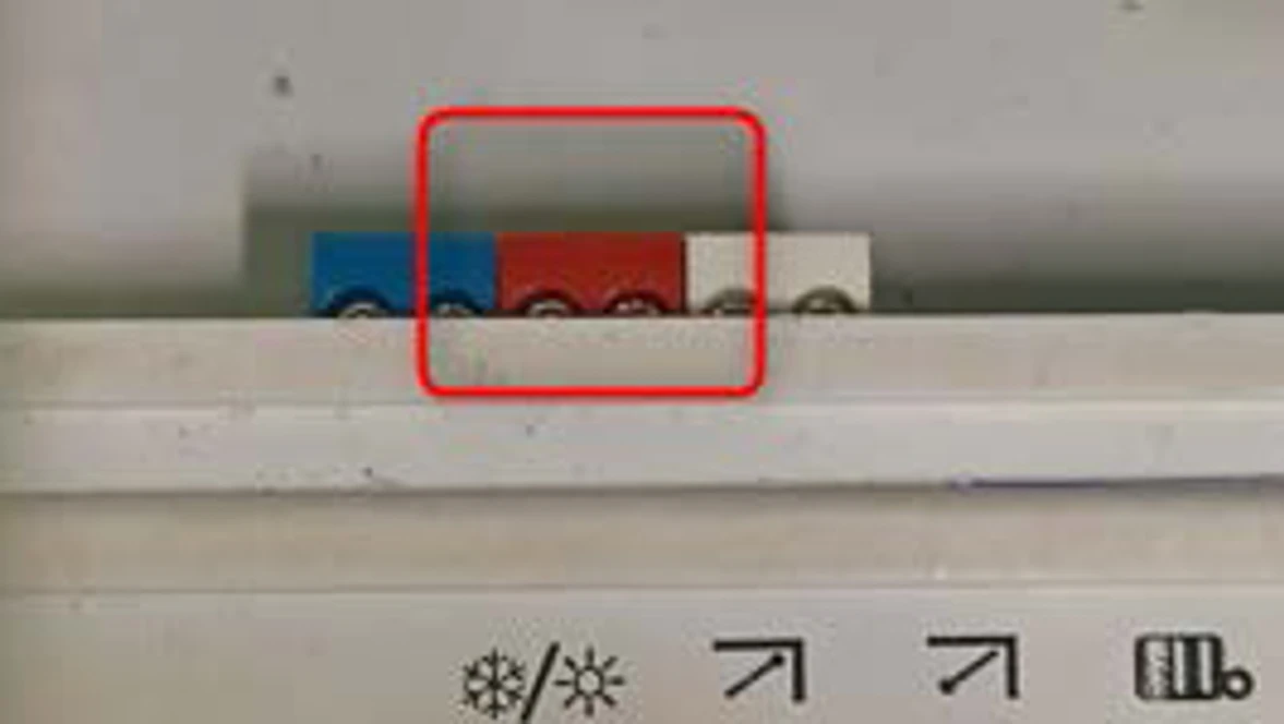
Results:
- If the jumper in the red connector causes the boiler to fire, there is an issue with the thermostat, end switch or thermostat wire. These are outside the boiler, field installed, so you will need to troubleshoot the issue.
- If the jumper in the red connector does not cause the boiler to fire, contact the Bosch technical support specialists.
Greenstar Boiler Diagram
Greenstar Boiler Diagram
A7 Code
A7 Code
Tools Needed
Digital Multi-meter
Hand Tools
Error Code Information
| Models | ZWB28, ZWB35, ZWB42, KWB28, KWB35, KWB42, ZBR16, ZBR28, ZBR35, ZBR42 KBR16, KBR28, KBR35, KBR42 |
| Error Code | A7 |
| Error Code Meaning | Control no longer gets a reading from the DHW sensor |
| Possible Causes |
Broken wire to sensor Failed sensor Incorrect code plug |
Troubleshooting Steps
Step 1. Check wire connections
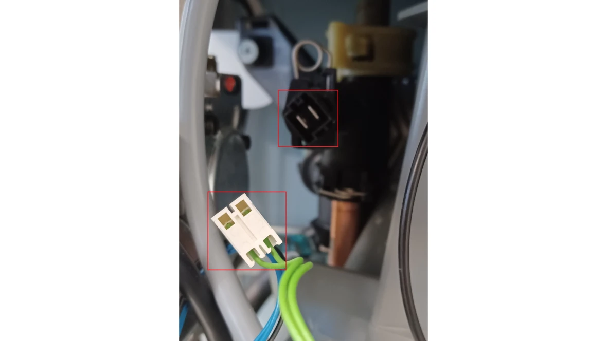
- Check the wiring to the domestic hot water sensor for pinched wires or broken or loose connections.
Results:
- If there were any loose or disconnected wires, re-seat the connections to ensure they are tight and reset the error code.
- If there are any damaged wires, the component with the damaged wire will need to be replaced.
- If the wire connections are all tight and there is no damage to the wires, go to step 2.
Step 2. Measure the resistance of the Domestic Hot Water Sensor
- Locate the domestic hot water sensor which is located between the gas valve and the condensate trap
- The DHW sensor has a white plug with two green wires connected to it
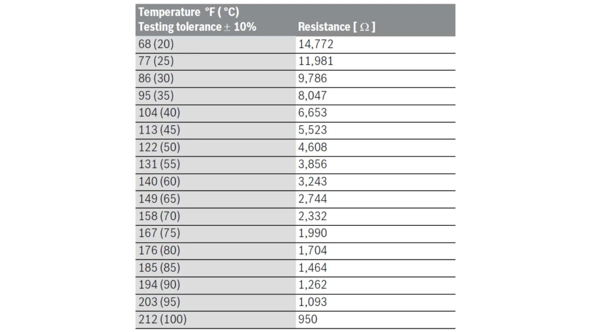
- A good sensor will have a resistance reading that measures in thousands of ohms and can be compared to the chart from the installation manual.
Results:
- If the sensor measures O/L or a reading that is not on the chart above the sensor is faulty and
- needs to be replaced. The part number is available through the Aftermarket Resource Center.
If the sensor measures correctly contact a Bosch Technical Support Specialist
A8 Code
A8 Code
Tools Needed
Digital Multi-meter
Hand Tools
Error Code Information
| Models | ZWB28, ZWB35, ZWB42, KWB28, KWB35, KWB42, ZBR16, ZBR28, ZBR35, ZBR42 KBR16, KBR28, KBR35, KBR42 |
| Error Code | A8 |
| Error Code Meaning | Communication fault or BUS device on BB |
| Possible Causes |
Incorrect thermostat wiring Failed heatronic control |
Troubleshooting Steps
Check wiring to the BUS/BB terminal
- Are they using a conventional thermostat (one that only acts like a switch without communication)?
- Yes - Make sure the wires from the thermostat are wired to 2 and 4 on the wall boiler or TT on the floor boiler and the factory jumper is removed from those connections.
- No - Contact a Bosch Technical Support Specialist
Ad Code
Ad Code
Tools Needed
Digital Multi-meter
Hand Tools
Error Code Information
| Models | ZWB28, ZWB35, ZWB42, KWB28, KWB35, KWB42, ZBR16, ZBR28, ZBR35, ZBR42 KBR16, KBR28, KBR35, KBR42 |
| Error Code | Ad |
| Error Code Meaning | DHW tank temperature not detected |
| Possible Causes |
Broken wire Faulty sensor Faulty control board |
Troubleshooting Steps
Step 1. Verify wire connections
- Is the tank sensor wire connected to the sensor and the boiler?
Wall Boiler Sensor Connection
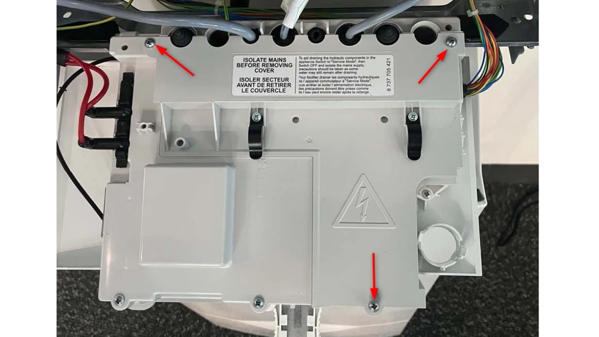
- Remove the 3 Phillips screws behind the control to expose the circuit board underneath.
- Once the cover is removed, confirm the blue wires on the right side of the board are making a tight connection.
Floor Boiler Sensor Location
- On the back of the boiler, remove two screws to open up the low voltage connection box.
- Confirm the two wires from the tank sensor connected into the top of where the two blue wire connections are tight.
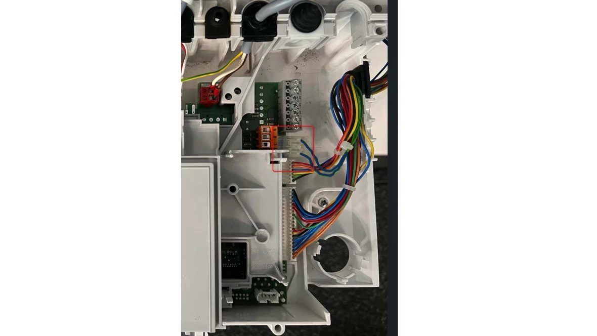
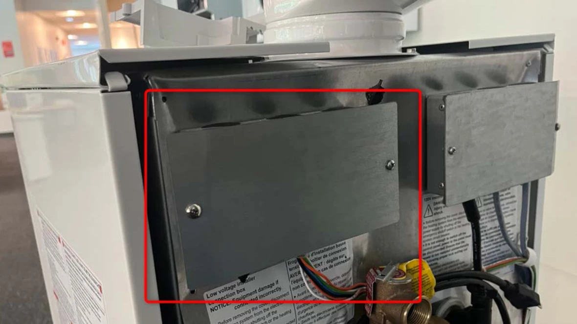
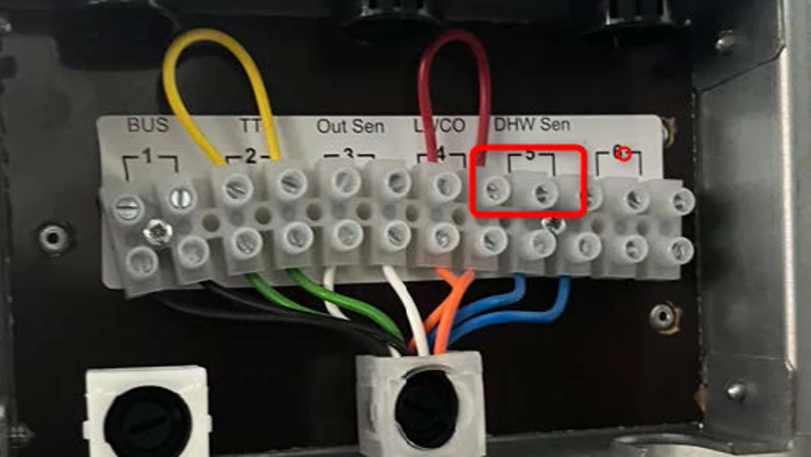
Results:
- If the wire connections are tight, go to step 2.
- If the wire connections are not tight, tighten the wire connections, reset the code and see if the issue comes back. If the issue comes back, go to step 2.
Step 2. Check sensor resistance
- Use the chart in the installation manual to measure Ohms resistance (no K or M ohms) of the tank sensor and compare to the temperature they should be reading.
Wall Boiler Sensor Testing
- Disconnect the two blue wire connection from the board and put a probe on each of the two screws to get a resistance reading.
Floor Boiler Sensor Testing
- Disconnect the sensor where the two wires connect into the top of the terminal block that is marked DHW Sensor and put each probe on a wire of the sensor to get a resistance reading.
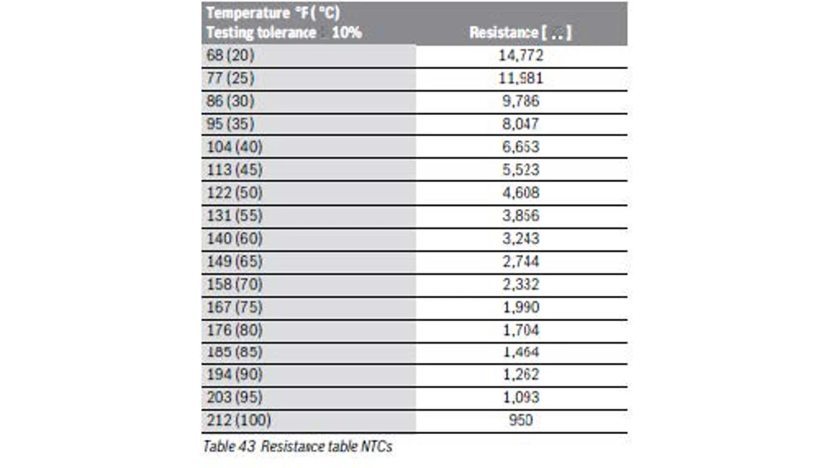
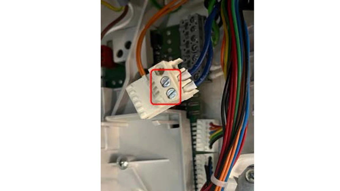
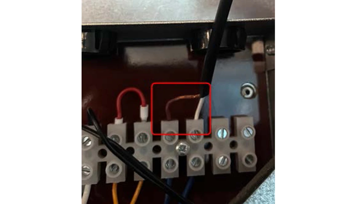
Results:
- Does the resistance readings match the chart in the Installation manual?
- If no, the sensor is bad and will need to be replaced. You can find the part number through our Aftermarket Resource Center.
- If yes, contact the Bosch Technical Support Specialists.
B1 Code
B1 Code
Tools Needed
Hand Tools
Error Code Information
| Models | ZWB28, ZWB35, ZWB42, KWB28, KWB35, KWB42, ZBR16, ZBR28, ZBR35, ZBR42 KBR16, KBR28, KBR35, KBR42 |
| Error Code | B1 |
| Error Code Meaning | Code plug (conversion plug) not detected |
| Possible Causes |
Faulty Code Plug Code Plug not installed Code Plug not inserted correctly |
Troubleshooting Steps
Step 1 - Verify the code plug is installed.
- Turn off power to the boiler.
- Locate the code plug on the green control board.
- Pull the plug out and put it back in place to ensure a tight connection.
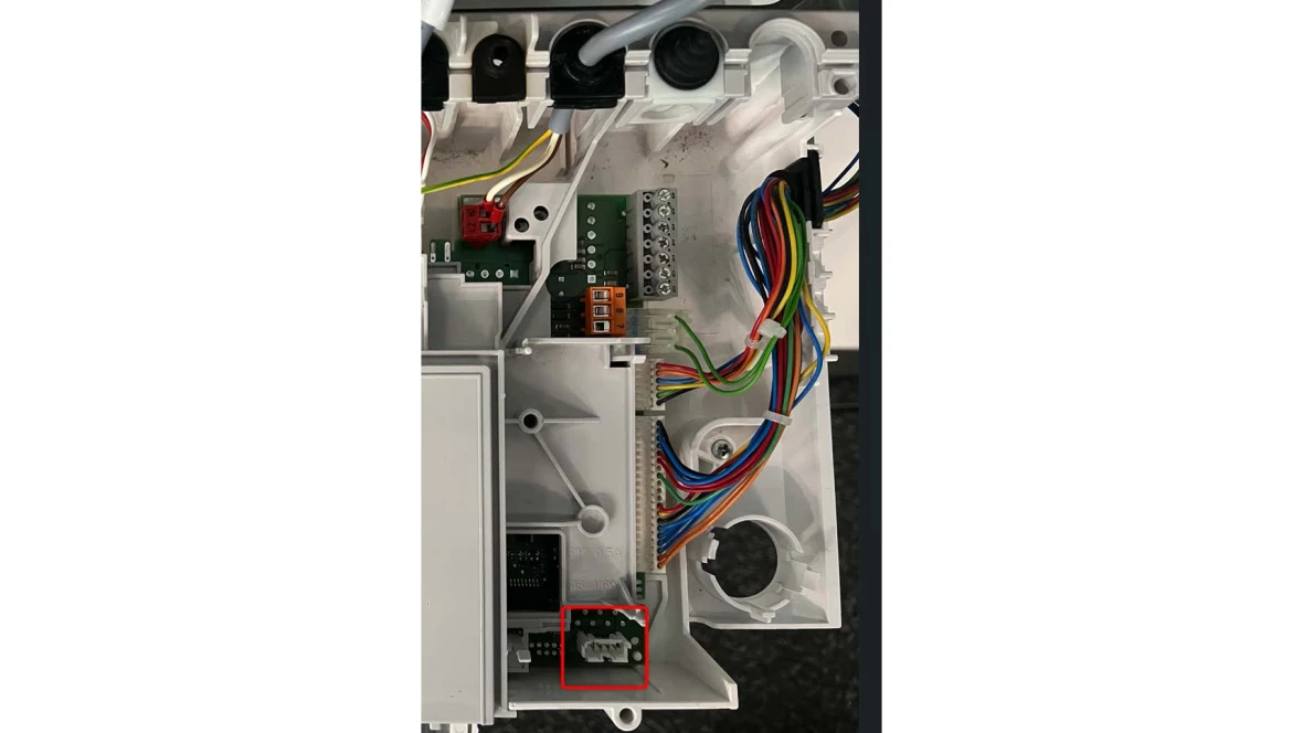
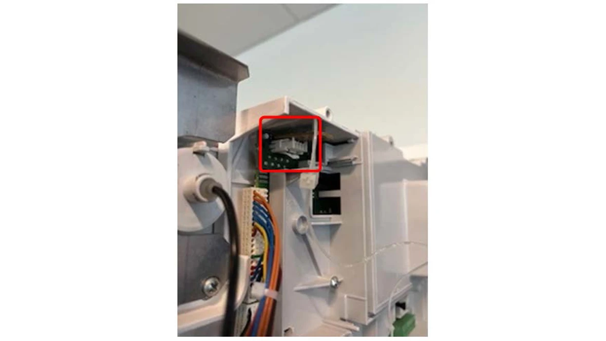
Results:
- If the error code goes away when the power is turned back on, it was a connection issue.
- If the error code doesn't go away when the power is turned back on, Contact a Bosch Technical Support Specialist
B2, B3, B4, B5, B6 Error Codes
B2, B3, B4, B5, B6 Error Codes
Tools Needed
Hand Tools
Error Code Information
| Models | ZWB28, ZWB35, ZWB42, KWB28, KWB35, KWB42, ZBR16, ZBR28, ZBR35, ZBR42 KBR16, KBR28, KBR35, KBR42 |
| Error Code | B2, B3, B4, B5, B6 |
| Error Code Meaning | Internal data error |
| Possible Causes | Faulty Control Board |
Troubleshooting Steps
Step 1 - Verify wire connections
- Turn off power to the boiler.
- Ensure all wire connections to the board are tight.
Results:
- If the error code goes away when the power is turned back on, it was a connection issue.
- If the error code doesn't go away when the power is turned back on, go to step 2
Step 2 - Perform a factory reset of the boiler
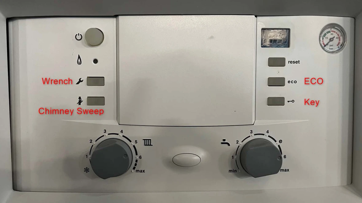
- With the power on, hold down the wrench button until it lights up.
- Once the button lights up, you should see a 1.A on the screen. Let go of the wrench button.
- Hold the ECO and key buttons until the display changes to 8.A.
- From 8.A use the ECO button to go to 8.E.
- When at 8.E, push and release the chimney sweep button. 00 will appear on the screen.
- Hold down the chimney sweep button. When you see brackets "[ ]" on the screen, let go of the chimney sweep button. NOTE: If the button is held in too long, the chimney sweep button will light up and the display will show "==". This is test fire mode. You will need to push the chimney sweep button three times to get back to boiler temperature.
- That should bring you back to 8.E.
- Push the wrench button to get back to boiler temperature on the display.
Results:
- If you have successfully factory reset the boiler, it will go through its initial start up process of air purge and trap fill. This can take up to 20 minutes.
- If the boiler is working at that point, the issue has been resolved.
- If the error comes back, the heatronic control needs to be replaced. The part number is available through the Aftermarket Resource Center.
C6 Code
C6 Code
Tools Needed
Digital Multi-meter
Hand Tools
Error Code Information
| Models | ZWB28, ZWB35, ZWB42, KWB28, KWB35, KWB42, ZBR16, ZBR28, ZBR35, ZBR42 KBR16, KBR28, KBR35, KBR42 |
| Error Code | C6 |
| Error Code Meaning |
Fan not running NOTE: If the code comes up intermittently, replace the fan. |
| Possible Causes |
Bad fan Bad fan leads |
Troubleshooting Steps
Step 1. Verify power to the fan
- Reset the error code.
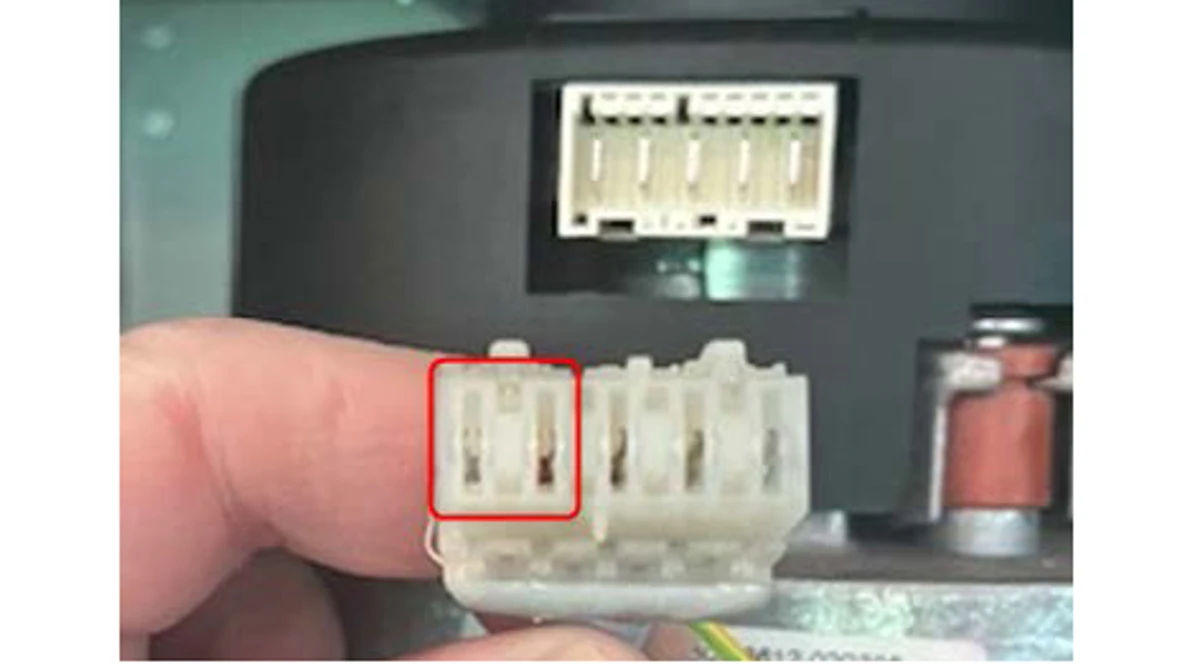
- Disconnect the 5 wire plug from the fan. With the clips on the top of the connector, test the two connections on the left for VAC. This needs to be completed before the C6 error code comes up. The unit won't put power to the fan if there is an error code on the screen.
Results:
- If you measure 120 (+/- 10%) VAC and the fan is not running, the fan is bad and needs to be replaced. The part number is available through the Aftermarket Resource Center.
- If you don't get 120 (+/-10%) VAC, go to step 2.
Step 2. Ohm the wire harness to the fan
- Disconnect the wiring harness from the fan and the control board.
- Using the ohms setting on your digital multi-meter, ohm out each wire connection.
Results:
- If you get continuity (not OL) through all the wires, it's a bad heatronic control. The part number is available through the Aftermarket Resource Center.
- If don't get continuity or OL on one or more of the wires, replace the fan wiring harness. The part number is available through the Aftermarket Resource Center.
CC Code
CC Code
Tools Needed
Digital Multi-meter
Hand Tools
Error Code Information
| Models | ZWB28, ZWB35, ZWB42, KWB28, KWB35, KWB42, ZBR16, ZBR28, ZBR35, ZBR42 KBR16, KBR28, KBR35, KBR42 |
| Error Code | CC |
| Error Code Meaning | Outdoor temperature sensor not recognized |
| Possible Causes |
Failed Outdoor Sensor Failed Wire to Outdoor Sensor |
Troubleshooting Steps
Step 1. Test the outdoor sensor for ohms
- Disconnect the two wires going to the outdoor sensor.
- Set your digital multi-meter to regular ohms and test the sensor for ohms.
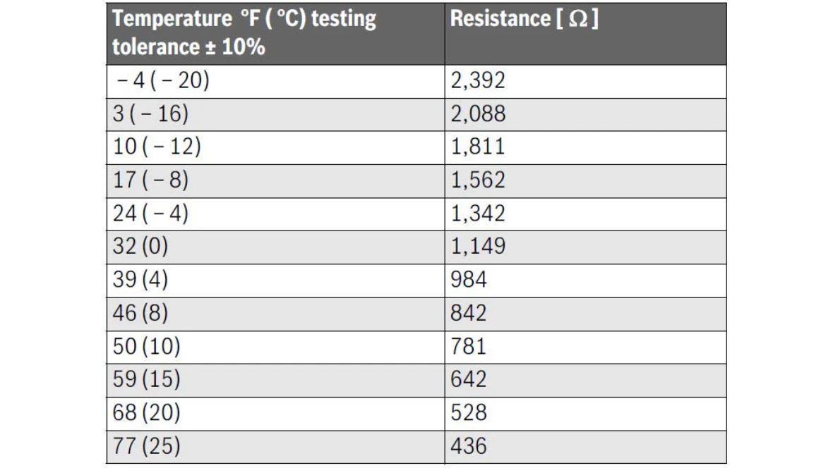
- Use the chart in the installation manual to compare the ohm reading you get with the temperature where the sensor is.
Results:
- If the ohm reading doesn't match the temperature, replace the outdoor sensor. You can find the part number through our Aftermarket Resource Center.
- If you get the appropriate ohm reading, go step 2.
Step 2. Ohm the wire from the boiler to the outdoor sensor
- Disconnect the wires for the outdoor sensor from the boiler.
- Wall boiler - This is connected to the control board.
- Floor boiler - This is connected to the terminal block on the back of the boiler.
- Using the ohms setting on your digital multi-meter, ohm out each wire connection.
Results:
- If you get continuity (not OL) through all the wires, it's a bad heatronic control. You can find the part number through our Aftermarket Resource Center.
- If you don't get continuity or OL on one or more of the wires, replace the thermostat wire that runs between the boiler and the outdoor sensor. Thermostat wire is not provided with the boiler, so you will have to source it locally.
D3 Code
D3 Code
Tools Needed
Digital Multi-meter
Hand Tools
Error Code Information
| Models | ZWB28, ZWB35, ZWB42, KWB28, KWB35, KWB42, ZBR16, ZBR28, ZBR35, ZBR42 KBR16, KBR28, KBR35, KBR42 |
| Error Code | D3 |
| Error Code Meaning | The boiler is low on water |
| Possible Causes |
Low water cutoff (LWCO) is faulty Boiler is low on water No power to the LWCO Air in the system |
Troubleshooting Steps
Step 1. Verify that there is water pressure in the boiler.
- Use the gauge on the boiler to see what the water pressure is.
Results:
- If the gauge is in the red, add water to the system and check for leaks. No parts are needed.
- If the gauge is green, go to step 2.
Step 2. Bleed air from the system.
- Use the bleeder valve or purge valve to bleed the air from the system.
Results:
- If bleeding the system removes the code, no parts are needed.
- If bleeding the system doesn't remove the code, go to step 3.
Step 3. Verify if the issue is the LWCO circuit or the boiler.
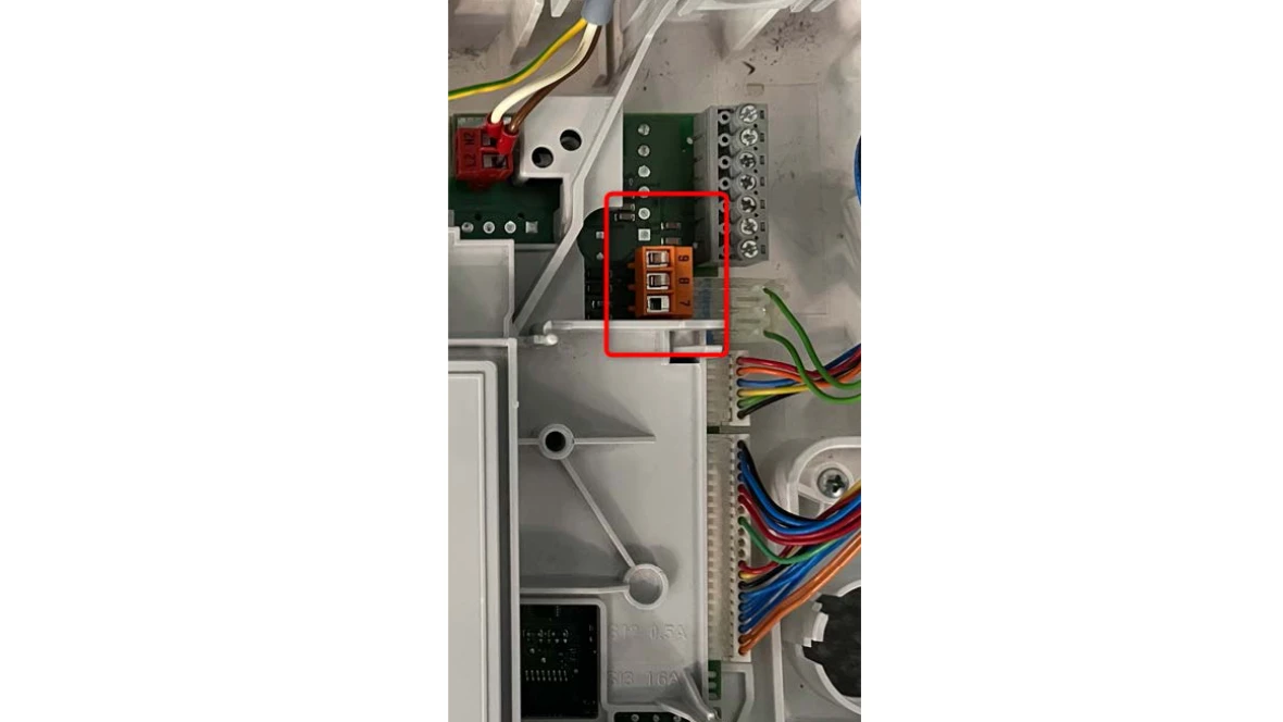
- Jump the LWCO end switch.
- Wall Boiler - This is done at the orange terminal at 8 & 9 on the control board.
- Floor Boiler - This is done at the low voltage terminal block on the back of the boiler.
Note: The red wire in the picture is there from the factory and will be removed if a LWCO is installed.
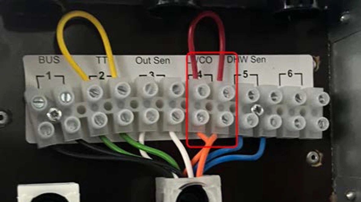
Results:
- If the boiler fires, the issue is with the LWCO circuit. You will need to focus on the LWCO along with it's wiring which is not provided by Bosch.
- If the boiler does not fire or clear the code, its a bad control board. You can find the part number through our Aftermarket Resource Center.
D5 Code
D5 Code
Tools Needed
Digital Multi-meter
Hand Tools
Error Code Information
| Models | ZWB28, ZWB35, ZWB42, KWB28, KWB35, KWB42, ZBR16, ZBR28, ZBR35, ZBR42 KBR16, KBR28, KBR35, KBR42 |
| Error Code | D5 |
| Error Code Meaning | The control board is looking for an external temperature sensor, but not seeing one. |
| Possible Causes |
Defective sensor Broken wire Defective control board |
Troubleshooting Steps
Step 1. Verify ohm reading of the temperature sensor.
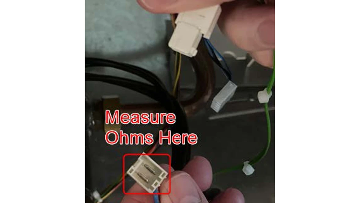
- The external temperature sensor will be attached to the piping of the low loss header. This is located in different places for the wall and floor versions.
Wall boiler
- On the Greenstar wall boiler, the sensor will be on the field installed header, on the supply pipe.
- Locate the sensor and follow the wire to the sensor wire disconnect.
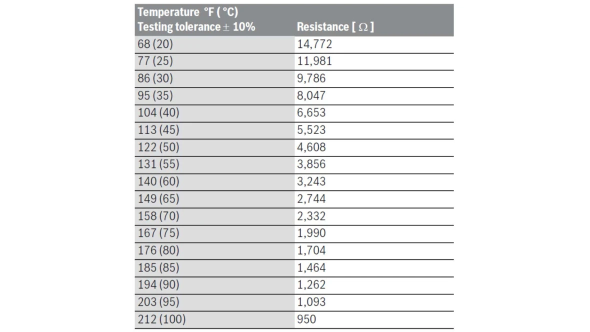
- Disconnect the wire and measure the K ohms on the sensor side of the disconnect and compare to the resistance chart in the installation manual.
Floor boiler
- On the Greenstar floor boiler, the sensor will be on the internally installed header, on the supply pipe.
- Locate the sensor and follow the wire to the sensor wire disconnect.
- Disconnect the wire and measure the K ohms on the sensor side of the disconnect and compare to the resistance chart in the installation manual.
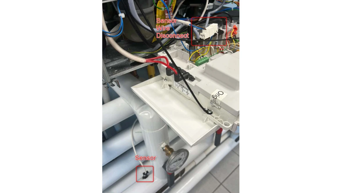
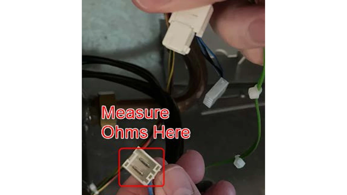
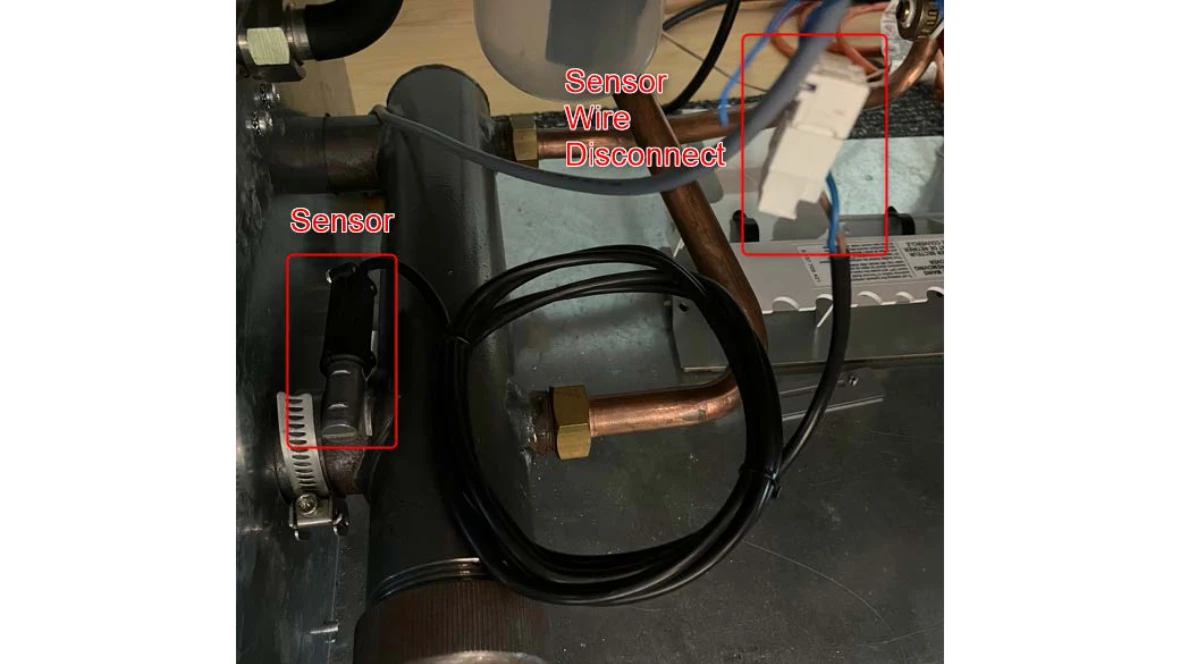
Results:
- If the ohms reading from the sensor doesn't match the temperature reading of the chart, it's a
- bad sensor. You can find the part number through our Aftermarket Resource Center.
- If the ohms reading from the sensor matches the temperature reading of the chart, go to step 2.
Step 2. Visually inspect the wire and sensor plug.
- Visually inspect the wire and the disconnect for any damage.
- Check the wire disconnect for any moisture.
Results:
- If the wire and/or the disconnect show any visual damage, you need a new sensor. You can find the part number through our Aftermarket Resource Center.
- If there is moisture in the disconnect, dry out the disconnect.
- If there is no visible damage or moisture present, go to step 3.
Step 3. Do a factory reset of the boiler
- With the power on, hold down the wrench button until it lights up.
- Once the button lights up, you should see a 1.A on the screen. Let go of the wrench button.
- Hold the ECO and key buttons until the display changes to 8.A.
- From 8.A you will use the ECO button to go to 8.E.
- When at 8.E, push and release the chimney sweep button. 00 will appear on the screen.
- Hold down the chimney sweep button. When you see brackets "[ ]" on the screen, you can let go of the chimney sweep button. NOTE: If the button is held in too long, the chimney sweep button will light up and the display will show "==". This is test fire mode. You will need to push the chimney sweep button three times to go back to boiler temperature.
- That should bring you back to 8.E.
- Push the wrench button to get back to boiler temperature on the display.
Results:
- If you have successfully factory reset the boiler, it will go through its initial start up process of air purge and trap fill. This can take up to 20 minutes.
- If the boiler is working at that point, the issue has been resolved.
- If the error comes back, the heatronic control needs to be replaced. You can find the part number through our Aftermarket Resource Center.
E2 Code
E2 Code
Tools Needed
Digital Multi-meter
Hand Tools
Error Code Information
| Models | ZWB28, ZWB35, ZWB42, KWB28, KWB35, KWB42, ZBR16, ZBR28, ZBR35, ZBR42 KBR16, KBR28, KBR35, KBR42 |
| Error Code | E2 |
| Error Code Meaning | Supply Temperature sensor is defective |
| Possible Causes |
Failed supply sensor Damaged wire Failed control board |
Troubleshooting Steps
Step 1. Verify the sensor is plugged in and the wires are not damaged.
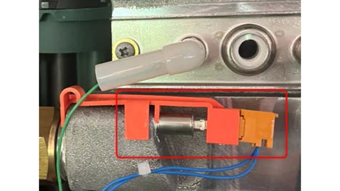
- The supply sensor is located on the heat exchanger, just below the electrodes.
- Visually inspect the wire for any damage.
- Disconnect the sensor connection, inspect for any rust/debris, then reconnect the sensor.
Results:
- If the wire for the sensor is damaged, you will need a new main wiring harness. You can find the part number through our Aftermarket Resource Center
- If there is rust/debris in the sensor connections, you will possibly need both a new sensor and new wiring harness. You can find the part numbers through our Aftermarket Resource Center
- If there is no sign of damage to the wire or rust/debris in the connection, go to step 2.
Step 2. Ohm out the sensor and compare resistance reading to temperature
- Disconnect the wires from the sensor and measure K ohms on the sensor.
- Compare the ohms readings to the temperature where the sensor is on the heat exchanger using the chart in the installation manual.
Results:
- If the sensor ohm reading does not match the temperature as noted on the chart, you have a bad sensor. The part number is available through the Aftermarket Resource Center.
- If the sensor ohm reading matches the temperature as noted on the chart, you have a bad heatronic control. The part number is available through the Aftermarket Resource Center.
E3 Code
E3 Code
Tools Needed
Digital Multi-meter
Hand Tools
Error Code Information
| Models | ZWB28, ZWB35, ZWB42, KWB28, KWB35, KWB42, ZBR16, ZBR28, ZBR35, ZBR42 KBR16, KBR28, KBR35, KBR42 |
| Error Code | E3 |
| Error Code Meaning | Additional supply temperature sensor defective |
| Possible Causes |
Failed additional supply sensor Damaged wire Failed control board. |
Troubleshooting Steps
Step 1. Verify the sensor is plugged in and the wires are not damaged.
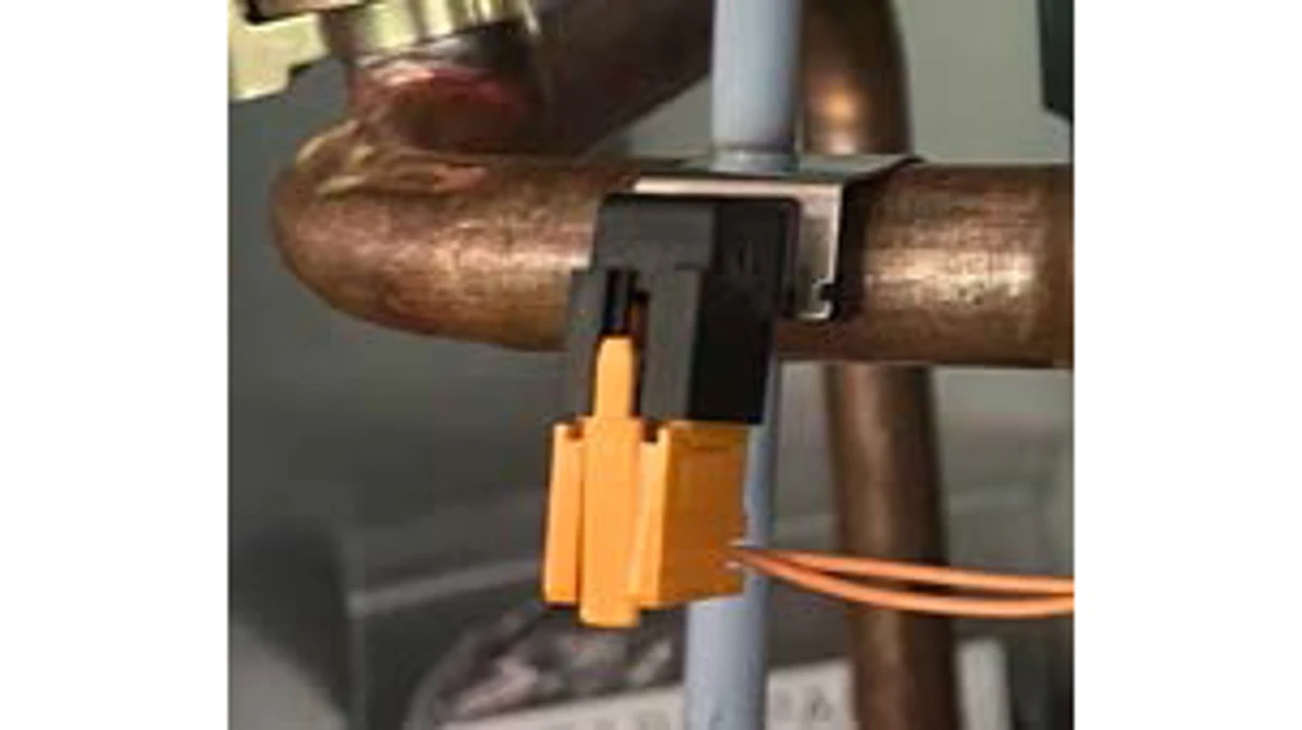
- The additional supply sensor is located on the pipe coming out of the top of the heat exchanger going to the left.
- Visually inspect the wire for any damage.
- Disconnect the sensor connection, inspect for any rust/debris, then reconnect the sensor.
Results:
- If the wire for the sensor is damaged, you will need a new main wiring harness. The part number is available through the Aftermarket Resource Center.
- If there is rust/debris in the sensor connections, you will possibly need both a new additional supply sensor and new wiring harness. The part number is available through the Aftermarket Resource Center.
- If there is no sign of damage to the wire or rust/debris in the connection, go to step 2.
Step 2. Ohm out the sensor and compare resistance reading to temperature
- Disconnect the wires from the sensor and measure K ohms on the sensor.
- Compare the ohms readings to the temperature where the sensor is on the heat exchanger using the chart in the installation manual
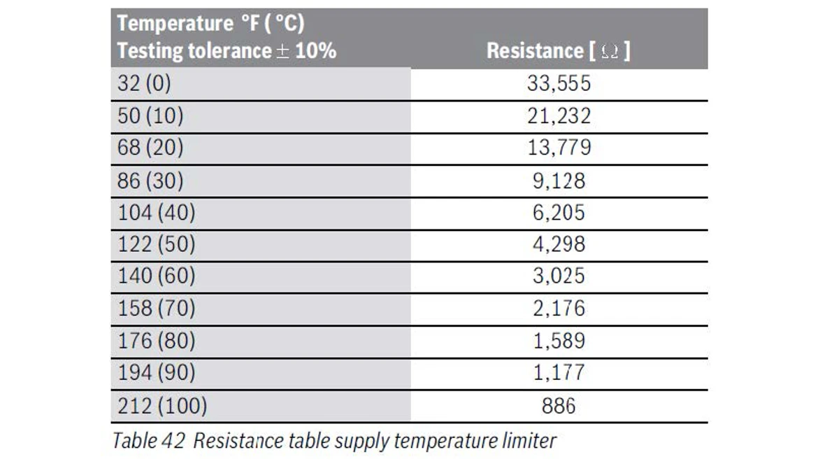
Results:
- If the sensor ohm reading does not match the temperature as noted on the chart, you have a bad sensor. The part number is available through the Aftermarket Resource Center.
- If the sensor ohm reading matches the temperature as noted on the chart, you have a bad heatronic control. The part number is available through the Aftermarket Resource Center.
E9 Code
E9 Code
Tools Needed
Hand Tools
Digital Multi-meter
Error Code Information
| Models | ZWB28, ZWB35, ZWB42, KWB28, KWB35, KWB42, ZBR16, ZBR28, ZBR35, ZBR42 KBR16, KBR28, KBR35, KBR42 |
| Error Code | E9 |
| Error Code Meaning |
Exhaust high limit tripped Boiler high limit tripped |
| Possible Causes |
Faulty exhaust sensor Faulty high limit sensor Faulty board Exhaust leaking on sensor |
Troubleshooting Steps
Step 1. Check Clean-Out Cover Bolts Are Tight
- Locate the 2 clean out cover bolts on the front of the boiler's heat exchanger.
- Tighten the bolts if they were loose. (The torque spec is 4.1 to 5.1 ft-lbs)
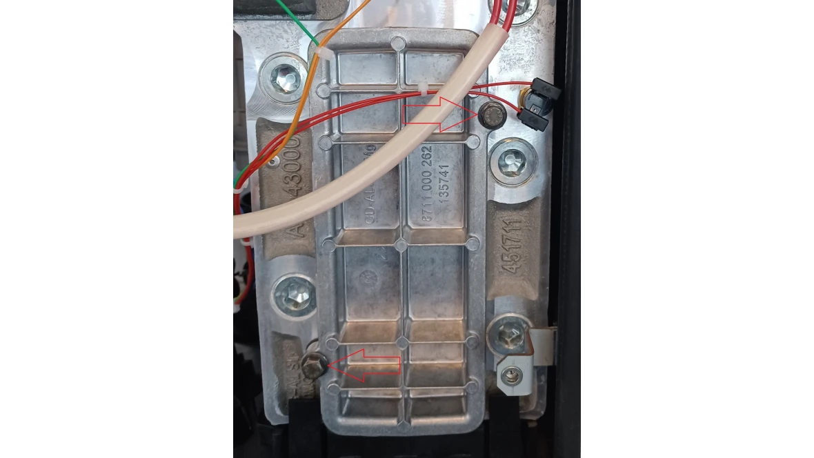
Results:
- If either of the bolts were loose the E9 code will likely go away.
- If the bolts were tight go to step 2.
Step 2. Inspect Wire And Plugs
- Locate the high limit switch on the front of the boiler block and check for any broken connectors, wires that aren't tight in the plugs, pinched or broken wires.
- Follow the red wires back to the control board checking for anything pinched or broken.
- Locate the exhaust high limit sensor that is attached to the condensate collector pan at the bottom of the unit and check for any broken connectors, wires that aren't tight in the plugs, pinched or broken wires etc.
- Follow the red wires back to the control board checking for anything pinched or broken.
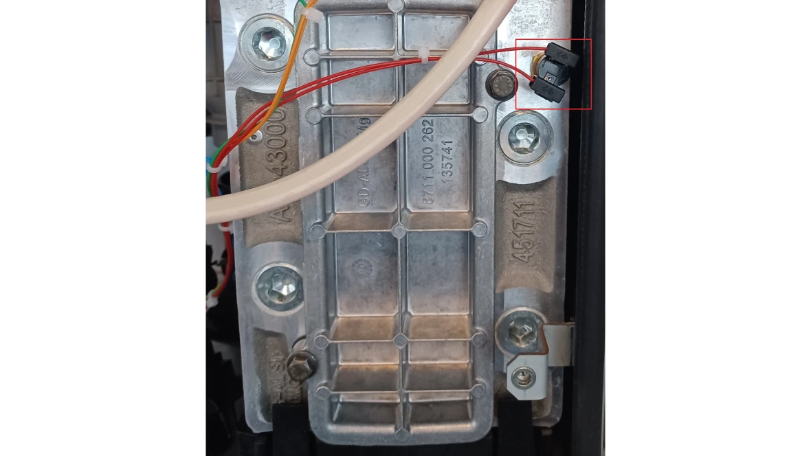
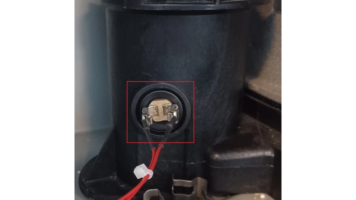
Results:
- If damage is found on the wires or the plugs the low voltage harness will need to be replaced.
- You can find the part number through our Aftermarket Resource Center.
- If there is no damage found on the wires or plugs go to step 3.
Step 3. Check Ohm's Reading of the Sensors
- Unplug both of the sensors in the previous steps and measure the resistance of each sensor by placing the probes on the metal tabs where the wires connect to them.
Results
- If the resistance of either sensor measures O/L that sensor is faulty and needs to be replaced.
- You can find the part number through our Aftermarket Resource Center.
- If the sensors measure anything other than O/L contact the Bosch Technical Support Specialists
EA Code
EA Code
Tools Needed
Digital Multi-meter
Combustion Analyzer
Gas manometer
Hand Tools
Error Code Information
| Models | ZWB28, ZWB35, ZWB42, KWB28, KWB35, KWB42, ZBR16, ZBR28, ZBR35, ZBR42 KBR16, KBR28, KBR35, KBR42 |
| Error Code | EA |
| Error Code Meaning | No flame detected during attempted ignition. GFA: Safety time expired. |
| Possible Causes |
Flames are not igniting Dirty flame sensor Disconnected wire |
Troubleshooting Steps
Step 1. Check inlet gas pressure
- Shut off power to the boiler.
- Using a manometer, measure the inlet gas pressure on the bottom port of the gas valve. Shut the gas supply off, turn the screw counterclockwise 2 full turns, slide the manometer hose over the port, and then re open gas supply.
Results:
- If the gas pressure measures between the ranges below, go to step 2.
- Natural Gas (NG) = 3.5" - 10.5" WC
- Liquid Propane (LP) = 8" - 13" WC
- If the gas pressure does not fall within the ranges noted above, there is a gas supply issue. A trained professional will need to identify the issue within the gas supply system.
Step 2. Inspect the electrode assembly.
- At the top of the heat exchanger is the electrode assembly. It contains the flame sensor, sight glass and sparking electrodes
- Remove the electrode assembly (one screw on either side of it).
- Inspect the flame sensor and sparking electrodes for pitting, build up, corrosion or warping.
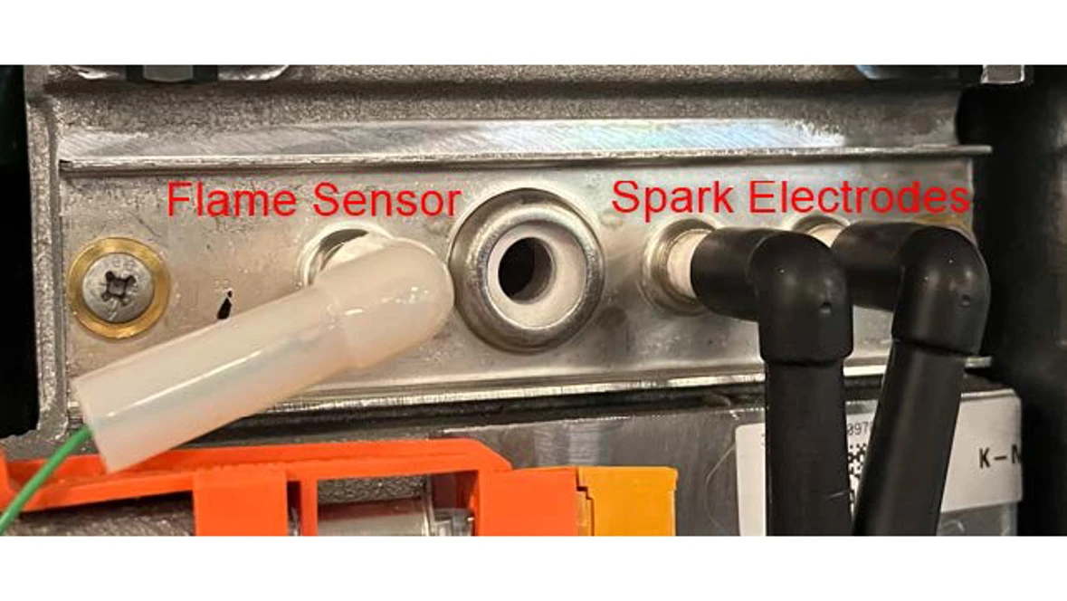
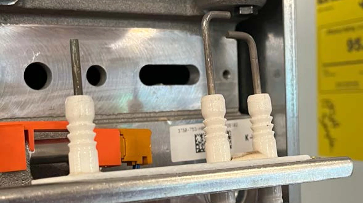
Results:
- If the flame sensor or spark electrodes are worn, corroded or warped, replace the electrode assembly. The part number is available through the Aftermarket Resource Center.
- If the electrode assembly is in good condition, go to step 3.
Step 3. Check that the condensate is draining
- Locate the condensate trap in the bottom of the cabinet
- There is a silver tab holding the condensate trap onto the bottom side of the cabinet.
- Pull the tab downward and pull the assembly towards you.
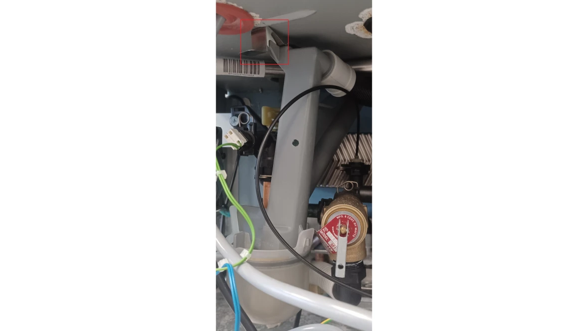
Results:
- If a lot of water came out when you removed the assembly inspect the condensate removal path for blockages and clear them.
- If no water came out reattach the condensate trap and go to step 4.
Step 4. Inspect Diaphragm valve
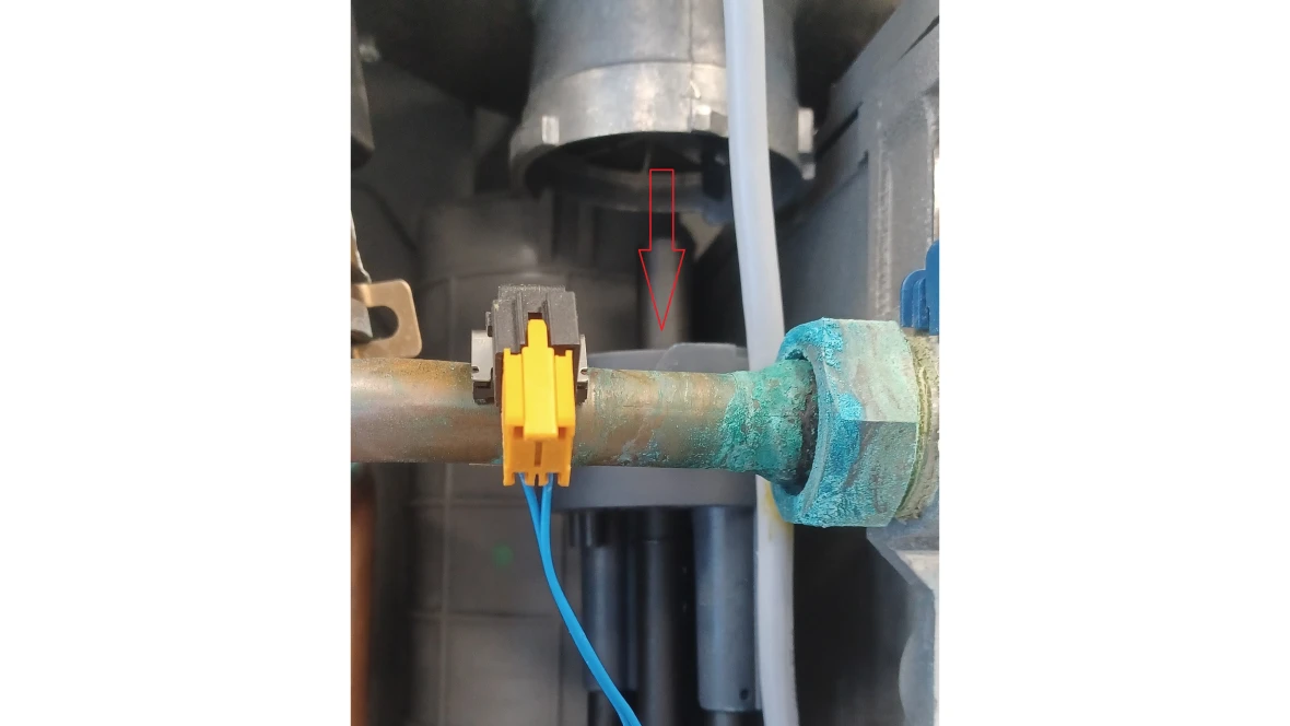
- Locate the air mixing cup that is to the left of the electrode assembly and attached to the bottom of the fan.
- Note this cup may be grey, green, or maroon in color.
- Twist the cup to loosen from the fan assembly and slide it down the center gas tube as far as you can.
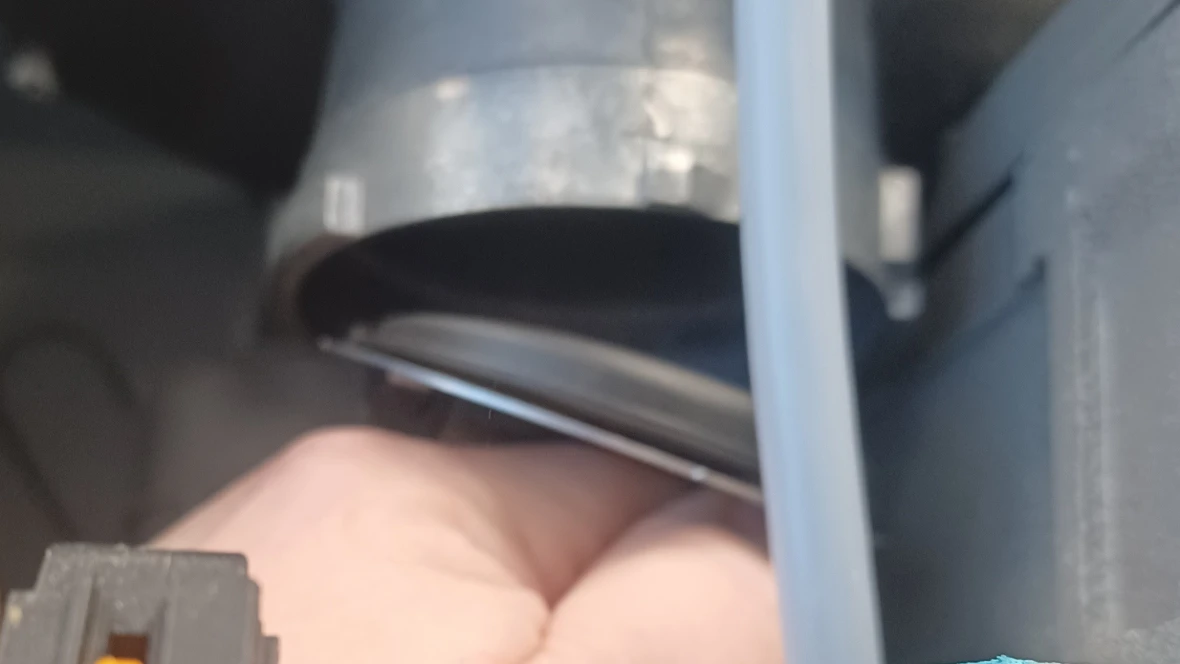
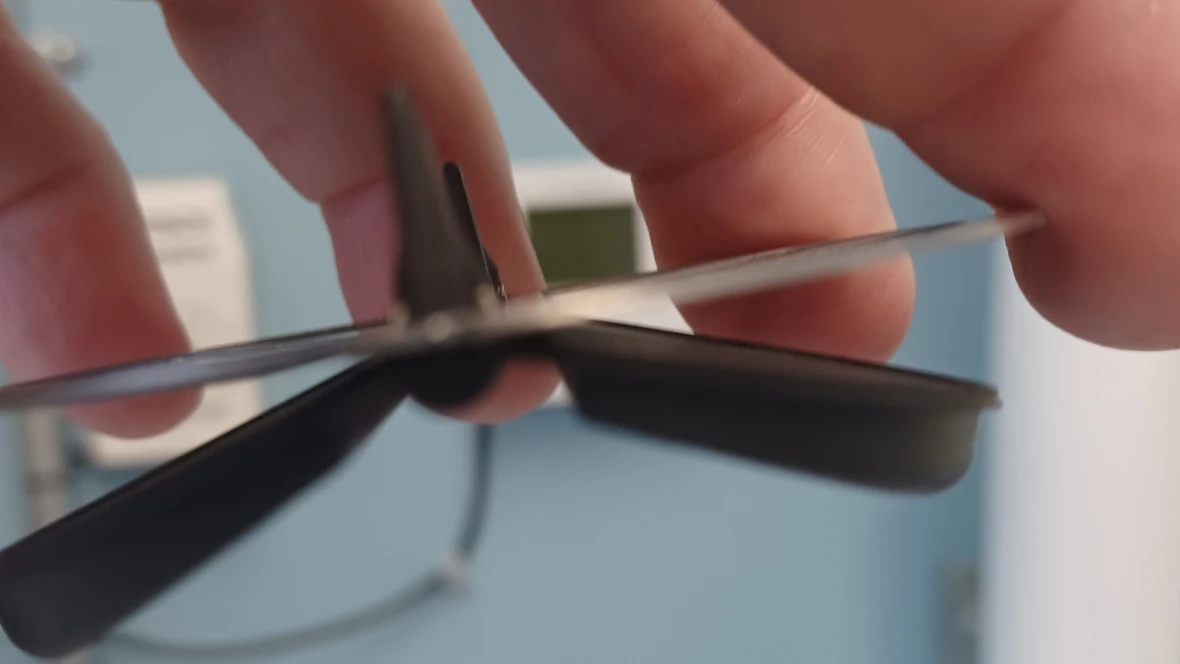
- Locate and remove the diaphragm valve that is inside the fan assembly
- Inspect the diaphragm valve for damage and ensure that the rubber flaps aren't sticking to the metal frame at all.
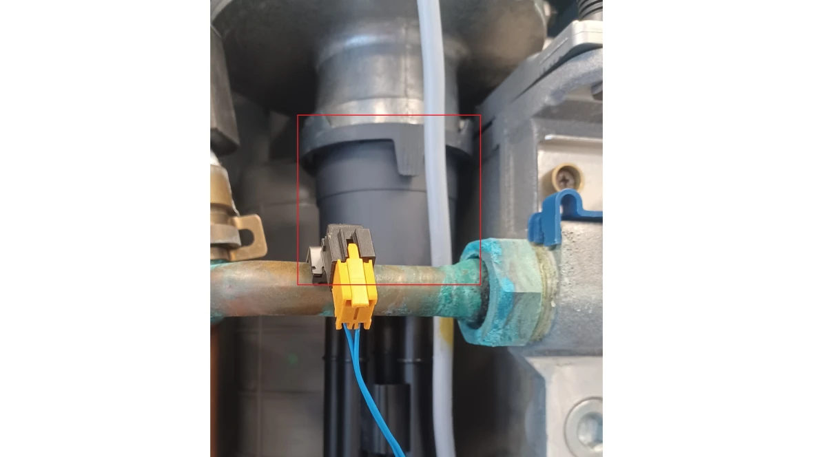
Results:
- If the diaphragm valve is damaged replace it. The part number is available through the Aftermarket Resource Center.
- If the diaphragm valve is sticking free it up and gently clean it with soap and water. Dry off completely before reinstalling.
- If the diaphragm valve was free, reinstall all components and contact a Bosch Technical Support Specialist
F0 Code
F0 Code
Tools Needed
Hand Tools
Digital Multi-meter
Error Code Information
| Models | ZWB28, ZWB35, ZWB42, KWB28, KWB35, KWB42, ZBR16, ZBR28, ZBR35, ZBR42 KBR16, KBR28, KBR35, KBR42 |
| Error Code | F0 |
| Error Code Meaning | Internal data error |
| Possible Causes | Failed heatronic control |
Troubleshooting Steps
Step 1. Check voltage to the heatronic control
- Floor Boiler
- Set your digital multi-meter to VAC.
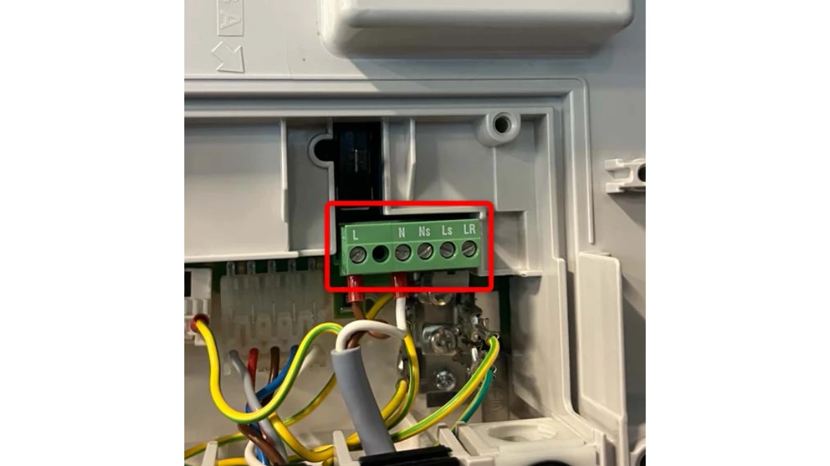
- Open the back of the heatronic control and locate the green terminal block.
- Measure from the "L" terminal to the "N" terminal.
- Wall Boiler
- Set your digital multi-meter to VAC.
- Open the back of the heatronic control and locate the green terminal block.
- Measure from the "L" terminal to the "N" terminal.
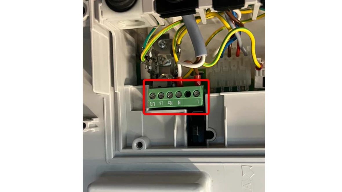
Results:
- If the reading is 120 VAC (+/- 10%), go to step 2.
- If the reading is not 120 VAC (+/- 10%), there is a problem with the power supply coming into the boiler that you will need to resolve.
Step 2. Do a factory reset of the boiler
- With the power on, hold down the wrench button until it lights up.
- Once the button lights up, you should see a 1.A on the screen. Let go of the wrench button.
- Hold the ECO and key buttons until the display changes to 8.A.
- From 8.A you will use the ECO button to go to 8.E.
- When at 8.E, you will push and release the chimney sweep button. 00 will appear on the screen.
- Hold down the chimney sweep button. When yoyu see brackets "[ ]" on the screen, you can let go of the chimney sweep button. NOTE: If the button is held in too long, the chimney sweep button will light up and the display will show "==". This is test fire mode. You will need to push the chimney sweep button three times to go back to boiler temperature.
- That should bring you back to 8.E.
- Push the wrench button to get back to boiler temperature on the display.
Results:
- If you have successfully factory reset the boiler, it will go through its initial start up process of air purge and trap fill. This can take up to 20 minutes.
- If the boiler is working at that point, the issue has been resolved. The part number is available through the Aftermarket Resource Center.
- If the error comes back, the heatronic control needs to be replaced. The part number is available through the Aftermarket Resource Center.
F1 Code
F1 Code
Tools Needed
Hand Tools
Digital Multi-meter
Error Code Information
| Models | ZWB28, ZWB35, ZWB42, KWB28, KWB35, KWB42, ZBR16, ZBR28, ZBR35, ZBR42 KBR16, KBR28, KBR35, KBR42 |
| Error Code | F1 |
| Error Code Meaning | Internal data error |
| Possible Causes | Failed heatronic control |
Troubleshooting Steps
Step 1. Check voltage to the heatronic control
- Floor Boiler
- Set your digital multi-meter to VAC.
- Open the back of the heatronic control and locate the green terminal block.
- Measure from the "L" terminal to the "N" terminal.
- Wall Boiler
- Set your digital multi-meter to VAC.
- Open the back of the heatronic control and locate the green terminal block.
- Measure from the "L" terminal to the "N" terminal.
Results:
- If the reading is 120 VAC (+/- 10%), go to step 2.
- If the reading is not 120 VAC (+/- 10%), there is a problem with the power supply coming into the boiler that you will need to resolve
Step 2. Do a factory reset of the boiler
- With the power on, hold down the wrench button until it lights up.
- Once the button lights up, you should see a 1.A on the screen. Let go of the wrench button.
- Hold the ECO and key buttons until the display changes to 8.A.
- From 8.A you will use the ECO button to go to 8.E.
- When at 8.E, you will push and release the chimney sweep button. 00 will appear on the screen.
- Hold down the chimney sweep button. When yoyu see brackets "[ ]" on the screen, you can let go of the chimney sweep button. NOTE: If the button is held in too long, the chimney sweep button will light up and the display will show "==". This is test fire mode. You will need to push the chimney sweep button three times to go back to boiler temperature.
- That should bring you back to 8.E.
- Push the wrench button to get back to boiler temperature on the display.
Results:
- If you have successfully factory reset the boiler, it will go through its initial start up process of air purge and trap fill. This can take up to 20 minutes.
- If the boiler is working at that point, the issue has been resolved. The part number is available through the Aftermarket Resource Center.
- If the error comes back, the heatronic control needs to be replaced. The part number is available through the Aftermarket Resource Center.
F7 Code
F7 Code
Tools Needed
Hand Tools
Digital Multi-meter
Error Code Information
| Models | ZWB28, ZWB35, ZWB42, KWB28, KWB35, KWB42, ZBR16, ZBR28, ZBR35, ZBR42 KBR16, KBR28, KBR35, KBR42 |
| Error Code | F7 |
| Error Code Meaning | Flame detected even when burner is off |
| Possible Causes |
Faulty worn or corroded flame rod Faulty or wet control board Loose ground in boiler |
Troubleshooting Steps
Step 1. Inspect the electrode assembly.
At the top of the heat exchanger is the electrode assembly. It contains the flame sensor, sight glass and sparking electrodes
Remove the electrodes (one philips screw on either side of it).
Inspect the flame sensor and sparking electrodes for pitting, build up, corrosion or warping.
Results:
- If the flame sensor or spark electrodes are worn, corroded or warped, replace the electrode assembly. The part number is available through the Aftermarket Resource Center.
- If the electrode assembly is in good condition, go to step 2.
Step 2. Inspect the circuit board
- Remove the back of the heatronic control.
- Inspect the control for any moisture or loose wires.
Results:
- If there is moisture, dry out the board.
- If there are loose wires, reconnect them.
- If the board is in good condition and all wire connections are tight, reset the unit with the reset button.
- If the code doesn't go away, it's a bad control board. The part number is available through the Aftermarket Resource Center.
FA Code
FA Code
Tools Needed
Digital Multi-meter
Hand Tools
Gas Manometer
Error Code Information
| Models | ZWB28, ZWB35, ZWB42, KWB28, KWB35, KWB42, ZBR16, ZBR28, ZBR35, ZBR42 KBR16, KBR28, KBR35, KBR42 |
| Error Code | FA |
| Error Code Meaning | After switching gas off: Flame is detected |
| Possible Causes |
Faulty worn or corroded flame rod Faulty Gas Valve Faulty heatronic control Loose ground in boiler |
Troubleshooting Steps
Step 1. Inspect the electrode assembly.
- At the top of the heat exchanger is the electrode assembly. It contains the flame sensor, sight glass and sparking electrodes
- Remove the electrodes (one philips screw on either side of it).
- Inspect the flame sensor and sparking electrodes for pitting, build up, corrosion or warping.
Results:
- If the flame sensor or spark electrodes are worn, corroded or warped, replace the electrode assembly. The part number is available through the Aftermarket Resource Center.
- If the electrode assembly is in good condition, go to step 2.
Step 2. Visually inspect the burner
- Look through the sight glass in the electrode assembly when a call for heat stops to see if the burner goes out right away.
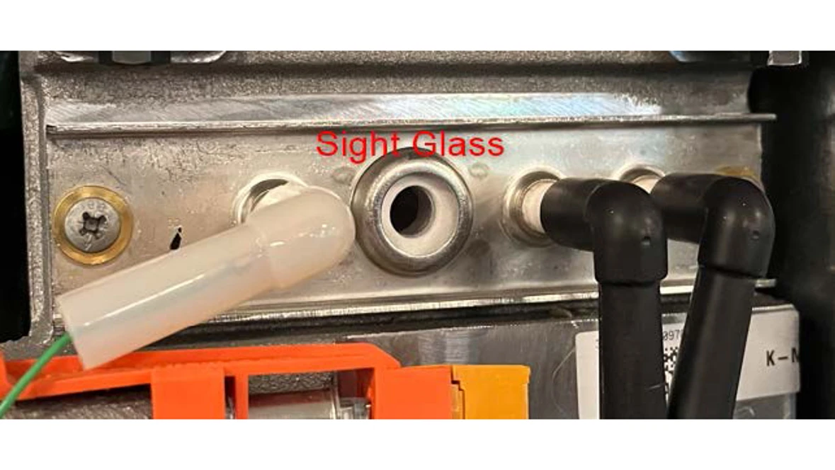
Results:
- If the flame does not go out right away, it's a bad gas valve. The part number is available through the Aftermarket Resource Center.
- If the flame does go out right away, it's a bad heatronic control. The part number is available through the Aftermarket Resource Center.
FD Code
FD Code
Tools Needed
Digital Multi-meter
Hand Tools
Error Code Information
| Models | ZWB28, ZWB35, ZWB42, KWB28, KWB35, KWB42, ZBR16, ZBR28, ZBR35, ZBR42 KBR16, KBR28, KBR35, KBR42 |
| Error Code | FD |
| Error Code Meaning | Reset button pressed by mistake |
| Possible Causes |
Reset button stuck Loose wire to board Faulty heatronic control |
Troubleshooting Steps
Step 1. Check wire connections
- Remove the cover off the back of the heatronic control.
- Confirm that all wire connections are tight.
Results:
- If there are any loose wires, re-seat the connections to ensure they are tight
- Once the wire connections are tight, reset the boiler with the reset button.
- If the boiler won't reset, go to step 2.
- If the wire connections are tight, reset the boiler with the reset button. If it won't reset, go to step 2.
Step 2. Do a factory reset of the boiler
- With the power on, hold down the wrench button until it lights up.
- Once the button lights up, you should see a 1.A on the screen. Let go of the wrench button.
- Hold the ECO and key buttons until the display changes to 8.A.
- From 8.A you will use the ECO button to go to 8.E.
- When at 8.E, you will push and release the chimney sweep button. 00 will appear on the screen.
- Hold down the chimney sweep button. When yoyu see brackets "[ ]" on the screen, you can let go of the chimney sweep button. NOTE: If the button is held in too long, the chimney sweep button will light up and the display will show "==". This is test fire mode. You will need to push the chimney sweep button three times to go back to boiler temperature.
- That should bring you back to 8.E.
- Push the wrench button to get back to boiler temperature on the display.
Results:
- If you have successfully factory reset the boiler, it will go through its initial start up process of air purge and trap fill. This can take up to 20 minutes.
- If the boiler is working at that point, the issue has been resolved.
- If the error comes back, the heatronic control needs to be replaced. The part number is available through the Aftermarket Resource Center.