
Gas Tankless Water Heaters Troubleshooting
A2 Error
A2 Error
Tools Needed
Digital Multi-meter
Hand Tools
Error Code Information
| Models |
250SX / 250SXO GWH 635ES / GWH 635ESO 2400E / 2400EO |
| Error Code | A2 |
| Error Code Meaning |
Fault in the flue gas limiter / overheat protection fault. An A2 error indicates a problem related to the overheat fuse/sensor in the upper half of the heater. More Info... On early heaters the sensor is a white overheat fuse that wraps around the heat exchanger. This sensor is designed to trip at approximately 355°F or 180°C. On newer heaters the sensor is a flue gas limiter that is mounted inside the upper right or left corner of the heater cabinet, above the copper heat exchanger (not to be confused with the green overheat sensor that mounts directly to the heat exchanger). The flue gas limiter is designed to trip if it senses temperatures exceeding 220°F or 104°C in the upper chamber of the heater. |
| Possible Causes |
Leak in the heat exchanger Bad sensor Bad wire connection. |
Troubleshooting Steps
NOTE: DO NOT jump out the fuse or sensor. Jumping the fuse or sensor is dangerous because it removes a critical safety circuit from the heater.
Step 1. Reset the error code
- Use the reset button to reset the error code.
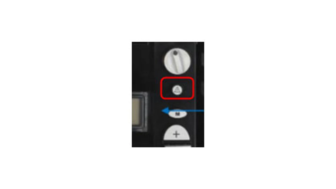
Result:
- If the error code resets, the sensor has cooled down, but will most likely trip again. Go to step 2.
- If the error code does not reset it could be an open sensor, leak in the heat exchanger or bad wire connection. Go to step 2.
Step 2. Verify wiring
- Older units may have a white wire wrapped around the heat exchanger. Verify if this white wire is plugged into the black wires connected to the control box.
- While looking for the white wire, look around the copper heat exchanger for signs of exhaust gases leaking from the
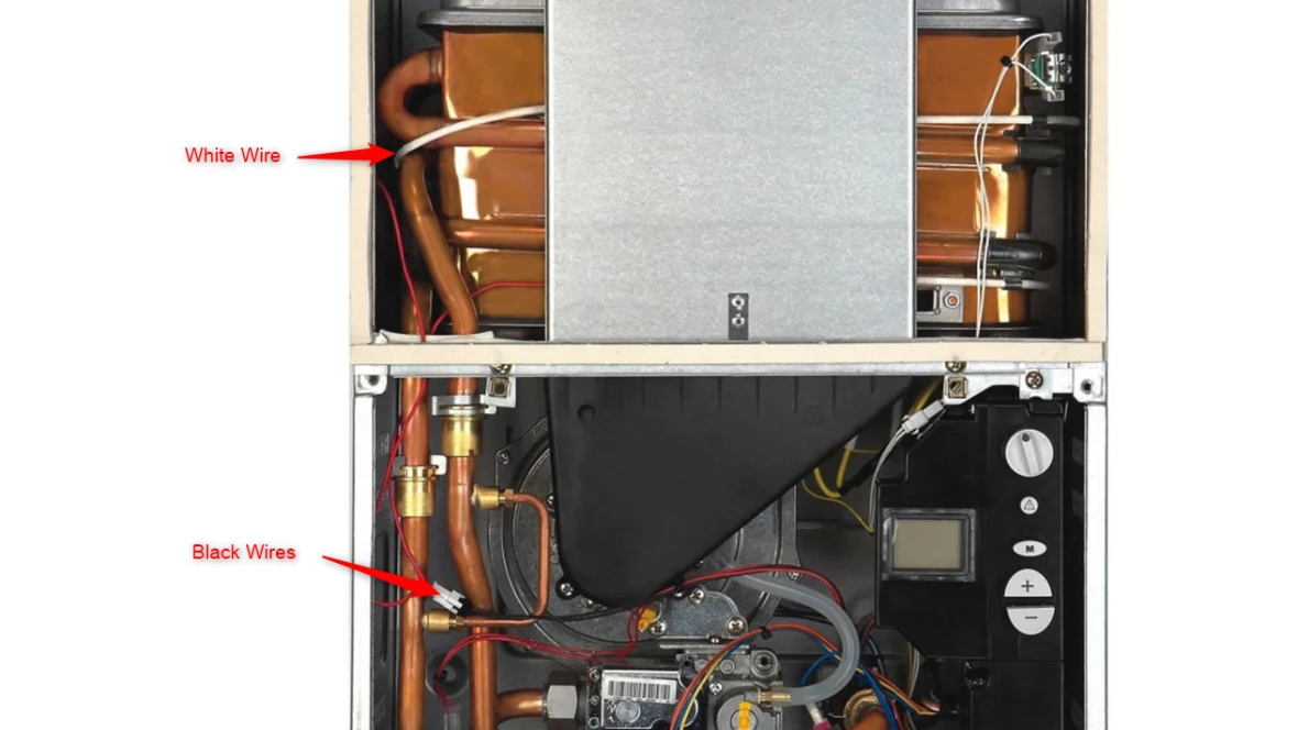
- If there are signs of an exhaust leak (anything burned, melted, scorched, etc.), contact the Bosch technical support specialists.
- If the white wire that is wrapped around the heat exchanger is plugged into the black wires leading to the control box and there are no signs of an exhaust leak, it's most likely the white wire got to close to the heat exchanger over time and has triggered the code.
- If the white wire wrapped around the heat exchanger is not connected to the control board, look to see if there is a sensor attached to the top left or right inside of the cabinet that is connected to white wires. See the pictures in bulletin TWH-G2-30 for further information.
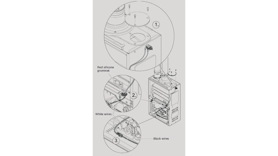
- If the flue gas limiter is installed, ensure tight wire connections.
- If the error code doesn't go away, contact the technical support specialists.
A7 Error
A7 Error
Tools Needed
Digital Multi-meter
Basic hand tools (wrench, screwdriver, etc.)
Error Code Information
| Models |
250SX / 250SXO GWH 635ES / GWH 635ESO 2400E / 2400EO |
| Error Code | A7 |
| Error Code Meaning |
Hot water temperature sensor/receiver defect An A7 error indicates a problem related to the hot water sensor (located on the hot water pipe at the bottom of the unit). |
| Possible Causes | The sensor may be sensing temperatures outside normal parameters, the unit needs to be serviced or the sensor itself may be defective. |
Troubleshooting Steps
DO NOT automatically assume a bad sensor. The error may be legitimate and the heater may be trying to tell us that is sensing temperatures out of range.
Step 1. Has the unit ever been maintained/serviced?
- If yes, go to step 2
- If no, service the unit by doing a descale treatment and removing the heat exchanger to clean the combustion chamber.
Step 2
- Ensure the two red wires leading to the sensor are connected tightly and the sensor is firmly clipped to the hot water pipe. The sensor should be clipped to the top, middle of the horizontal section of the hot water pipe. Check the temperature sensor and contacts for corrosion. Clean contacts with light sandpaper or an eraser.
Results:
- If corroded badly, the sensor will need to be replaced.
- If everything is clean and connected as it should be, go to step 3.
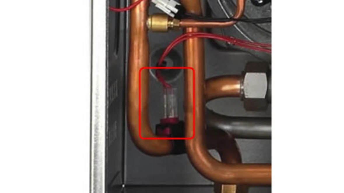
Step 3
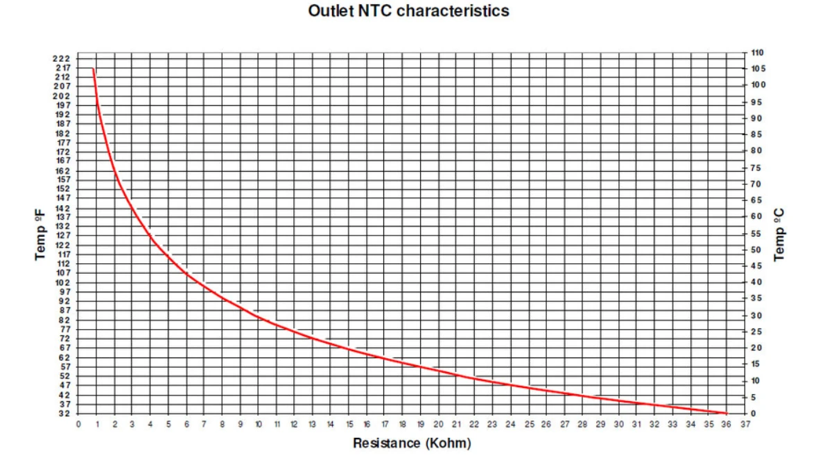
- Ohm out the sensor using the temperature sensor chart in the manual to compare the temperature of the water to the K ohm reading of the sensor. This can be completed by removing the wires from the sensor and placing the probes of the meter on the metal tabs on the sensor.
- Does the K ohm reading match the temperature reading?
Results:
- If yes, contact the Bosch technical support specialists.
- If no, the sensor will need to be replaced.
A9 Error
A9 Error
Tools Needed
Digital Multi-meter
Basic hand tools (wrench, screwdriver, etc.)
Error Code Information
| Models |
250SX / 250SXO GWH 635ES / GWH 635ESO 2400E / 2400EO |
| Error Code | A9 |
| Error Code Meaning |
Outlet temperature sensor not sensing set temperature An A9 error indicates that the hot water temperature sensor is not sensing the expected outlet temperature. The error code may flash on the display while the heater continues to run or it may shut off the heater, requiring the error code to be reset. |
| Possible Causes | There are a variety of potential causes for the A9. A9 may be caused by a temperature undershoot or overshoot. A bad or mispositioned hot water temperature sensor may also cause an A9 error. A9 can also be influenced by different control board software versions. |
Troubleshooting Steps
Step 1. Has the unit ever been maintained/serviced?
- If yes, go to step 2
- If no, service the unit by doing a descale treatment and removing the heat exchanger to clean the combustion chamber.
Step 2
- Ensure the two red wires leading to the sensor are connected tightly and the sensor is firmly clipped to the hot water pipe. The sensor should be clipped to the top, middle of the horizontal section of the hot water pipe. Check the temperature sensor and contacts for corrosion. Clean contacts with light sandpaper or an eraser.
Results:
- If corroded badly, the sensor will need to be replaced.
- If everything is clean and connected as it should be, go to step 3.
Step 3
- Ohm out the sensor using the temperature sensor chart in the manual to compare the temperature of the water to the K ohm reading of the sensor. This can be completed by removing the wires from the sensor and placing the probes of the meter on the metal tabs on the sensor.
- Does the K ohm reading match the temperature reading?
Results:
- If yes, contact the Bosch technical support specialists.
- If no, the sensor will need to be replaced.
C1 Error
C1 Error
Tools Needed
Digital Multi-meter
Basic hand tools (wrench, screwdriver, etc.)
Error Code Information
| Models |
250SX / 250SXO GWH 635ES / GWH 635ESO 2400E / 2400EO |
| Error Code | C1 |
| Error Code Meaning |
Fan rotation too low at start-up A C1 error indicates the fan speed is too low (out of parameters) during attempted start-up. |
| Possible Causes | C1 is not a common error. There is not a common cause for the C1 error. |
Troubleshooting Steps
Note: A C1 error can occasionally occur if another error is not reset properly or if the heater is turned on and off quickly while the fan is still purging. A one-time error under these circumstances should not be a concern.
Step 1. Check the fan for damage, debris or water.
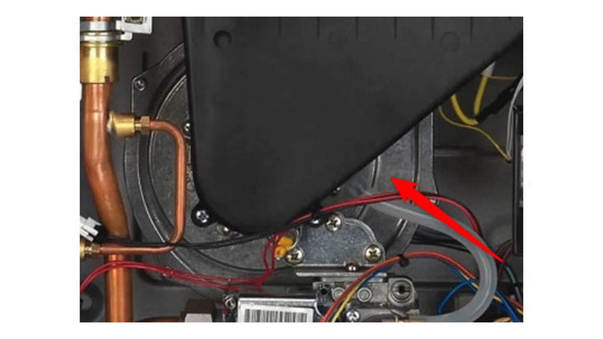
- The blower fan is located in the bottom half of the unit and has a black air scoop on the front of it.
- Remove a metal bar that goes across the middle of the unit by removing the two screws, one on either end of the metal bar, to get the air scoop off the front of the fan by removing the two screws at the bottom of the scoop. Once removed, the inside of the fan can be inspected.
Results:
- If there is debris, remove it and reset the code. If the code comes back, go to step 2.
- If the fan is damaged, it will need to be replaced.
- If no damage, debris or water go to step 2.
Step 2. Check for blockage in the flue pipe.
Result:
- If no blockage, contact the Bosch technical support specialists.
C6 Error
C6 Error
Tools Needed
Digital Multi-meter
Basic hand tools (wrench, screwdriver, etc.)
Error Code Information
| Models |
250SX / 250SXO GWH 635ES / GWH 635ESO 2400E / 2400EO |
| Error Code | C6 |
| Error Code Meaning |
Fan rotation too low during operation A C6 error indicates the fan speed is too low (out of parameters) during attempted start-up |
| Possible Causes | C6 is not a common error. There is not a common cause for the C6 error. |
Troubleshooting Steps
Step 1. Check the fan for damage, debris or water.
- The blower fan is located in the bottom half of the unit and has a black air scoop on the front of it.
- The metal bar that goes across the middle of the unit will need to be moved by removing the two screws, one on either end of the bar, to get the air scoop off the front of the fan. Once removed, the inside of the fan will become visible.
Results:
- If there is debris, remove it and reset the code. If the code comes back, go to step 2.
- If the fan is damaged, it will need to be replaced.
- If no damage, debris or water go to step 2.
Step 2. Check for blockage in the flue pipe.
Result:
- If no blockage, contact the Bosch technical support specialists.
C7 Error
C7 Error
Tools Needed
Digital Multi-meter
Basic hand tools (wrench, screwdriver, etc.)
Error Code Information
| Models |
250SX / 250SXO GWH 635ES / GWH 635ESO 2400E / 2400EO |
| Error Code | C7 |
| Error Code Meaning |
No rotational speed sensor signal from fan A C7 error indicates that the heater is not sensing any fan speed |
| Possible Causes | C7 is not a common error, but can be associated with water or condensation damage in the heater due to improper installation. |
Troubleshooting Steps
If the fan assembly is damaged by water, DO NOT assume that replacing the fan will fix the heater. It is likely that other parts (particularly the gas valve) have also been damaged.
Step 1. Check the fan for damage, debris or water.
- The blower fan is located in the bottom half of the unit and has a black air scoop on the front of it.
- The metal bar that goes across the middle of the unit will need to be moved by removing the two screws, one on either end of the bar, to get the air scoop off the front of the fan. Once removed, the inside of the fan will become visible.
Results:
- If there is debris, remove it and reset the code. If the code comes back, go to step 2.
- If the fan is damaged, it will need to be replaced.
- If no damage, debris or water go to step 2.
Step 2. Check for blockage in the flue pipe.
Result:
- If no blockage, contact the Bosch technical support specialists.
CA Error
CA Error
Tools Needed
Digital Multi-meter
Basic hand tools (wrench, screwdriver, etc.)
Error Code Information
| Models |
250SX / 250SXO GWH 635ES / GWH 635ESO 2400E / 2400EO |
| Error Code | CA |
| Error Code Meaning |
Water flow signal over specified maximum value. A CA error indicates excessive water pressure or water flow (approx 10 gpm) through the heater |
| Possible Causes | CA is not a common error but is almost always related to unusually high inlet water pressures. This is usually not a heater problem, but instead is an external plumbing issue. |
Troubleshooting Steps
Step 1. Check the flow rate.
Results:
- If flowing over 10 GPM, the flow will need to be reduced.
- If not flowing over 10 GPM,contact the Bosch technical support specialists.
- Flow rate can be confirmed by getting a container with a known volume and timing how long it takes to fill.
E1 Error
E1 Error
Tools Needed
Digital Multi-meter
Basic hand tools (wrench, screwdriver, etc.)
Error Code Information
| Models |
250SX / 250SXO GWH 635ES / GWH 635ESO 2400E / 2400EO |
| Error Code | E1 |
| Error Code Meaning |
Over-temperature detected by hot water sensor E1 indicates the hot water sensor (located on the hot water pipe that leaves the heat exchanger) senses temperatures above 185 °F or 85 °C. |
| Possible Causes | E1 may indicate the heater is sensing very high outlet temps due to scale build-up or being fed pre-heated water. E1 may sometimes also indicate a defective hot water sensor. |
Troubleshooting Steps
DO NOT automatically assume a bad sensor. An overheat with an E1 error can be a serious issue. Be sure to verify all installation details and eliminate other variables before concluding that a temperature sensor is bad.
Step 1. Has the unit ever been maintained/serviced?
Results:
- Yes - Go to step 2
- No - Service the unit by doing a descale treatment and removing the heat exchanger to clean the burn chamber. The heat exchanger can be cleaned by using water from a hose and brushing off any debris from the burner bed while being careful of the ceramat layer (like a felt layer) on the burner itself. If the ceramat is damaged, the burner should be replaced.
Step 2
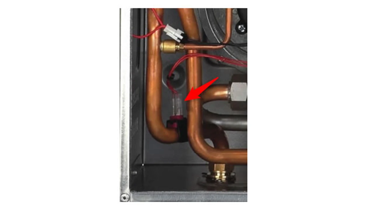
- Ensure the two red wires leading to the sensor are connected tightly and the sensor is firmly clipped to the hot water pipe. The sensor should be clipped to the top, middle of the horizontal section of the hot water pipe. Check the temperature sensor and contacts for corrosion. Clean contacts with light sandpaper or an eraser.
Results:
- If corroded badly, the sensor will need to be replaced.
- If everything is clean and connected as it should be, go to step 3.
Step 3
- Ohm out the sensor using the temperature sensor chart in the manual to compare the temperature of the water to the K ohm reading of the sensor. This can be completed by removing the wires from the sensor and placing the probes of the meter on the metal tabs on the sensor.
- Does the K ohm reading match?
Results:
- Yes - Contact the Bosch technical support specialists.
- No - The sensor is bad and needs to be replaced.
E2 Error
E2 Error
Tools Needed
Digital Multi-meter
Basic hand tools (wrench, screwdriver, etc.)
Error Code Information
| Models |
250SX / 250SXO GWH 635ES / GWH 635ESO 2400E / 2400EO |
| Error Code | E2 |
| Error Code Meaning |
Inlet temperature sensor fault An E2 error indicates a problem related to the cold water temperature sensor (located on the cold water pipe feeding the heat exchanger). |
| Possible Causes | The sensor may be sensing temperature outside normal parameters or the sensor itself may be defective. |
Troubleshooting Steps
DO NOT automatically assume a bad sensor. The error may be legitimate and the heater may be trying to tell us that it is sensing temperatures out of range.
Step 1. Has the unit ever been maintained/serviced?
Results:
- Yes - Go to step 2
- No - Service the unit by doing a descale treatment and removing the heat exchanger to clean the burn chamber. The heat exchanger can be cleaned by using water from a hose and brushing off any debris from the burner bed while being careful of the ceramat layer (like a felt layer) on the burner itself. If the ceramat is damaged, the burner should be replaced.
Step 2
- Ensure the two red wires leading to the sensor are connected tightly and the sensor is firmly clipped to the hot water pipe.
- The sensor should be clipped to the top, middle of the horizontal section of the hot water pipe. Check the temperature sensor and contacts for corrosion. Clean contacts with light sandpaper or an eraser.
Results:
- If corroded badly, the sensor will need to be replaced.
- If everything is clean as connected as it should be, go to step 3.
Step 3
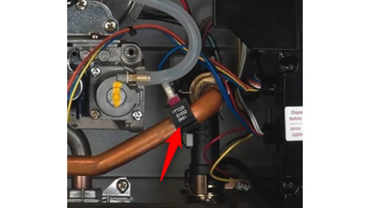
- The temperature sensors are the same on both the hot and cold water pipes. If you suspect a bad sensor, you can swap the hot and cold water sensor as a test (swap the sensors, not the wires).
Results:
- If swapping the sensors changes the error to A7, this indicates a bad sensor that should be replaced.
- If the error code doesn't change, go to step 4.
Step 4
- Ohm out the sensor using the temperature sensor chart in the manual to compare the temperature of the water to the K ohm reading of the sensor. This can be completed by removing the wires from the sensor and placing the probes of the meter on the metal tabs on the sensor.
- Alternately, you can clip both sensors on the same water pipe and take resistance readings off the sensors. Both sensors should be reading roughly the same resistance – if not, one sensor may be defective.
- Does the K ohm reading match?
Results:
- Yes - Contact the Bosch technical support specialists.
- No - The sensor is bad and needs to be replaced.
E9 Error
E9 Error
Tools Needed
Digital Multi-meter
Basic hand tools (wrench, screwdriver, etc.)
Error Code Information
| Models |
250SX / 250SXO GWH 635ES / GWH 635ESO 2400E / 2400EO |
| Error Code | E9 |
| Error Code Meaning |
Temperature limiter opened circuit (overheat) An E9 error indicates a problem related to the (green and white) overheat sensor (ECO) mounted on the upper right corner of the heat exchanger. The sensor is a safety device that is designed to break a circuit if it senses temps over 220 °F (104 °C). The sensor should reset itself after the heater has cooled off, but the error will still need to be reset with the reset button. |
| Possible Causes | E9 errors are typically caused by scale (mineral deposit) build-up in the heat exchanger and are often accompanied by banging or knocking noises from the heater. |
Troubleshooting Steps
DO NOT jump out the sensor. Jumping the sensor removes the critical safety circuit from the heater and puts the heater at risk of fire or explosion.
Step 1. Does the code reset after the unit cools down?
Results:
- Yes - Go to step 2
- No - The sensor is faulty and needs to be replaced.
Step 2. Has the machine been maintained?
Results:
- Yes - Contact the Bosch technical support specialists.
- No - Service the unit by doing a descale treatment and removing the heat exchanger to clean the burn chamber. The heat exchanger can be cleaned by using water from a hose and brushing off any debris from the burner bed while being careful of the ceramat layer (like a felt layer) on the burner itself. If the ceramat is damaged, the burner should be replaced.
EA Error
EA Error
Tools Needed
Digital Multi-meter
Basic hand tools (wrench, screwdriver, etc.)
Manometer
Error Code Information
| Models |
250SX / 250SXO GWH 635ES / GWH 635ESO 2400E / 2400EO |
| Error Code | EA |
| Error Code Meaning |
No ionization during safety time (safety time out) An EA error indicates that no burner flame is detected during an attempted start-up. The heater makes tree ignition attempts before going to an EA error code. |
| Possible Causes | EA can have a variety of causes, usually gasrelated. EA can be caused by no gas, air in the gas lines, low gas pressure, or a damaged gas valve. EA can also be caused by ignition spark or by a bad flame sensor. |
Troubleshooting Steps
Step 1. Is the gas pressure inside required ranged?
- Attached a manometer to the left hand port of the gas valve to get the gas pressure. Bulletin with details is here.
Results:
- Yes - Move to step 2.
- No - Gas supply needs to be fixed
NG = 5" - 14" water column, LP = 11" - 14" water column.
Step 2. Is the combustion chamber clean?
- Yes - Contact the Bosch technical support specialists.
- No - Service the unit by doing a descale treatment and removing the heat exchanger to clean the burn chamber. The heat exchanger can be cleaned by using water from a hose and brushing off any debris from the burner bed while being careful of the ceramat layer (like a felt layer) on the burner itself. If the ceramat is damaged, the burner should be replaced.
EC Error
EC Error
Tools Needed
Digital Multi-meter
Basic hand tools (wrench, screwdriver, etc.)
Manometer
Gas Analyzer
Error Code Information
| Models |
250SX / 250SXO GWH 635ES / GWH 635ESO 2400E / 2400EO |
| Error Code | EC |
| Error Code Meaning |
Ionization failure while burning (lose of burner flame) EC occurs when the heater senses a loss of flame (no ionization) during use. The ionization signal momentarily disappears more than 3 times in less than 30 seconds. |
| Possible Causes | EC typically occurs because of gas-related issues such as low gas pressures, improper air/ fuel (CO2) adjustments, dirty electrodes or a damaged gas valve. EC can be accompanied by groaning noises during start-up. |
Troubleshooting Steps
Step 1. Is the gas pressure inside required ranged?
- Have the caller attach their manometer to the left hand port of the gas Valve to get the gas pressure. Bulletin with details is here.
Results:
- Yes - Move to step 2.
- No - Gas supply needs to be fixed
NG = 5" - 14" water column, LP = 11" - 14" water column.
Step 2. Is the combustion chamber clean?
- Yes - Contact the Bosch technical support specialists.
- No - Service the unit by doing a descale treatment and removing the heat exchanger to clean the burn chamber. The heat exchanger can be cleaned by using water from a hose and brushing off any debris from the burner bed while being careful of the ceramat layer (like a felt layer) on the burner itself. If the ceramat is damaged, the burner should be replaced.
E0 Error
E0 Error
Tools Needed
Digital Multi-meter
Basic hand tools (wrench, screwdriver, etc.)
Error Code Information
| Models |
250SX / 250SXO GWH 635ES / GWH 635ESO 2400E / 2400EO |
| Error Code | E0 |
| Error Code Meaning |
Internal software/hardware failure E0 indicates a problem with a control board. A single E0 does not indicate a bad board, but repeated E0 errors may indicate a control board needs to be replaced. |
| Possible Causes | E0 may be caused by a bad circuit board or by a customer pressing the wrong combination of buttons while trying to reset an error or changing a setting on the heater. |
Troubleshooting Steps
Step 1. Is the machine plugged into an outlet by itself and on a dedicated circuit?
Results:
- Yes - Go to step 2.
- No - Try plugging the unit into another outlet that is on it's own dedicated circuit.
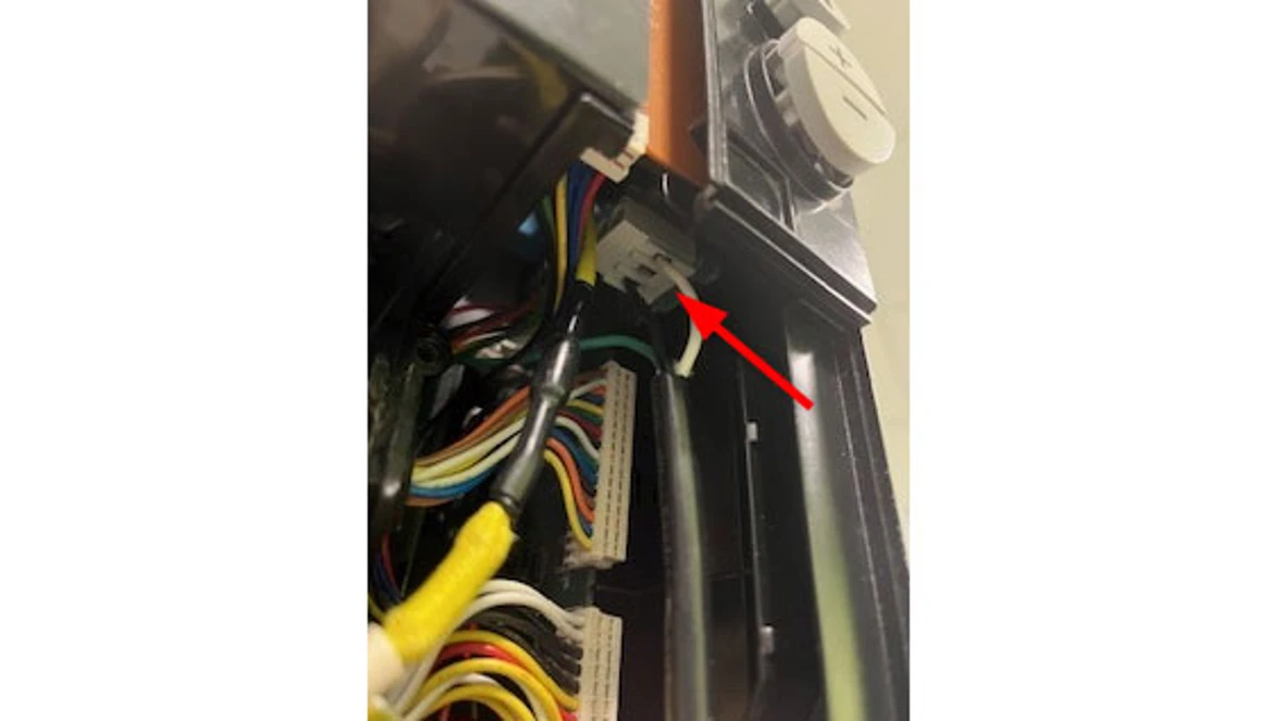
Step 2. Is the control board getting 120 VAC (-/+ 10%)?
- This can be tested where the plug is wired into the control box.
Results:
- Yes - Could be a bad control. Reset the unit and if it happens again, the control will need to be replaced.
- No - Have the power supply issue fixed.
F7 Error
F7 Error
Tools Needed
Digital Multi-meter
Basic hand tools (wrench, screwdriver, etc.)
Error Code Information
| Models |
250SX / 250SXO GWH 635ES / GWH 635ESO 2400E / 2400EO |
| Error Code | F7 |
| Error Code Meaning |
Ionization error (Flame sensing at standby) F7 indicates the heater thinks it is sensing burner flame while the heater is in standby mode. |
| Possible Causes |
F7 may indicate a damaged gas valve or a damaged flame sensor. This damage would most likely be caused by rain or condensate in the heater |
Troubleshooting Steps
Step 1. Has the flame sensor been removed and cleaned or replaced?
Results:
- Yes - Move to step 2.
- No - Remove the flame sensor to clean and inspect.
Step 2. Is the combustion chamber wet?
- Yes - Moisture is causing the code. Service the unit by removing the heat exchanger to check for leaks.
If there are any leaks, replace the heat exchanger. You can find the part number through - No - Update the record and transfer the qualified and onsite caller to the technical support specialists.
FA Error
FA Error
Tools Needed
Digital Multi-meter
Basic hand tools (wrench, screwdriver, etc.)
Manometer
Error Code Information
| Models |
250SX / 250SXO GWH 635ES / GWH 635ESO 2400E / 2400EO |
| Error Code | FA |
| Error Code Meaning |
Gas leakage error (gas valve does not close gas circuit) An FA error indicates the heater thinks it is still sensing flame after the heater shuts down. |
| Possible Causes |
FA may indicate a damaged gas valve or a damaged flame sensor. This damage would most likely be caused by rain or condensate in the heater. |
Troubleshooting Steps
Step 1. Do you see flame in the combustion chamber when the unit is shutting down after water flow stops?
Results:
- Yes - Move to step 2.
- No - Service the unit by removing the flame sensor to clean and inspect and removing the heat exchanger to clean the burn chamber. The heat exchanger can be cleaned using water from a hose and brushing off any debris from the burner bed while being careful of the ceramat (like a felt covering) on the burner itself. If the ceramat is damaged, the burner should be replaced.
Step 2. Is the gas pressure inside required ranged?
- Attach a manometer to the left hand port of the gas valve to get the gas pressure.
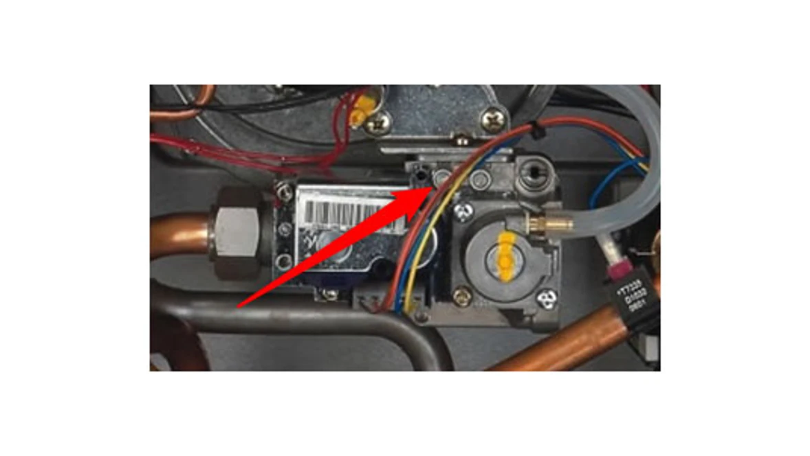
- Have the caller check gas pressure (NG = 5" - 14" water column, LP = 11" - 14" water column) and verify that the gas valve is dry.
- You can remove the cloud shaped plate with 3 screws just above the gas valve to confirm the existence of moisture in the gas valve.
Results:
- If the gas pressure is correct, the flame shuts off when water flow stops and there are no signs of moisture in the gas valve, contact the Bosch technical support specialists.
- If there is moisture behind the cloud shaped plate just above the gas valve, it's typically a sign of a leaking heat exchanger. Pull the heat exchanger to check for leaks and any are found, contact the Bosch technical support specialists.
8E Error
8E Error
Tools Needed
Digital Multi-meter
Basic hand tools (wrench, screwdriver, etc.)
Error Code Information
| Models |
250SX / 250SXO GWH 635ES / GWH 635ESO 2400E / 2400EO |
| Error Code | 8E |
| Error Code Meaning |
Electronic “noise” on circuit board. An 8E error indicates electronic “noise“ on the circuit board. A single 8E error does not indicate a bad board, but repeated errors may indicate a control board needs to be replaced. |
| Possible Causes | 8E can be caused by a customer pushing the wrong combination of buttons or may be caused by a defect on the circuit board. |
Troubleshooting Steps
Step 1. Does the code go away when reset?
Results:
- Yes - verify power supply, test operation of machine.
- No - Control will need to be replaced.
Burner does not ignite when hot
Burner does not ignite when hot
- If the display is blank, verify power to outlet. (120VAC/60Hz properly grounded circuit required). Verify that the heater power button is pressed ON.
- Verify the fuses in the control board are good. To access fuses, the control board must be removed.
- Make sure cold water inlet connection is plumbed to the right side of heater when facing unit.
- A minimum of 0.65 gallons per minute (GPM) (2,5 l/m) is required to activate the heater. A quart container should fill in 23 seconds or less, from hot water tap only, to activate heater.
- Clean inlet filter screen. Inspect the water path for obstructions. Make sure all showerheads, faucet aerators and whole house filters are clear of debris.
- The heater activates when the water flow through the unit is at or above the required minimum of 0.65 GPM (2,5 l/m). A crossover in the hot and cold plumbing pipes creates back pressure on the water flowing through the heater. Therefore, a higher flow rate than normal is needed to force the heater to activate. To check for a plumbing crossover, shut off the cold water supply to the water heater. Then open all of the hot water taps served by the heater. Wait 10 minutes and check for water flow at each tap. There should be no water flowing. Any continuous flow of water, small or large, indicates a crossover is present and must be corrected. Consult a professional plumber for help in correcting a crossover. Failing single lever faucet mixing valves are common causes of plumbing crossovers.
- With the power button pressed to OFF and the power supply cord unplugged, remove the unit's front cover. Check wire connections between the water valve, control unit and electrode set.
- Water heater in solar mode. If inlet water temperatures exceed the water heater's set temperature, the burners will not ignite and the solar mode indicator will show on the display.
Water is too hot
Water is too hot
- Selected temperature on the unit is too high. To lower output temperature, see chapter 5.4, page 32 of the manual.
- Clean inlet filter screen.
- Inspect the water path for obstructions. Make sure all showerheads, faucet aerators and whole house filters are clear of debris.
- Confirm that the heater's gas type coincides with the type of gas being supplied.
- Avoid restrictive outlets. Clean all showerheads and faucet aerators. It may be necessary to upgrade to higher flow rate shower heads if allowable by local code.
- In areas where the water has a high mineral content, periodic descaling may necessary.
- Ensure the outlet temperature sensor is making contact and firmly mounted on the hot water pipe.
Water is not hot enough
Water is not hot enough
- Selected temperature on the unit is too low. To raise output temperature, see chapter 5.4, page 32 of the manual.
- Clean inlet filter screen. See chapter 6.1, page 34 of the manual to increase flow through the heater.
- Inspect the water path for obstructions. Make sure all showerheads, faucet aerators and whole house filters are clear of debris.
- Confirm the heater's gas type coincides with the type of gas being supplied.
- Check inlet gas particle screen for blockage at gas inlet connection on bottom of unit.
- Verify gas pressure is in accordance with specifications in chapter 3.13, page 29 of the manual. A gas pressure reading is needed to proceed further.
- Contact your original installer or a local certified gas technician to obtain this reading.
- Cold water is mixing into the hot water lines (plumbing crossover). A plumbing crossover can unintentionally mix cold water with the hot water leaving the heater. The end result is a cooler water temperature than desired. To check for a plumbing crossover, shut off the cold water supply to the water heater. Then open all of the hot water taps served by the heater. Wait 10 minutes and check all taps for water flow. There should be no water flowing. Any continuous flow of water, small or large, indicates a crossover and must be corrected. Consult a professional plumber for help in correcting a crossover. Failing single lever faucet mixing valves are common causes of plumbing crossovers.
- Ensure the temperature sensor is making contact and firmly mounted on the hot water pipe.
Low water flow/pressure
Low water flow/pressure
- Too many hot water applications are being used simultaneously or too much flow is demanded. The water heater will effectively support two 2.0-2.5 GPM shower heads simultaneously or multiple sink applications. Greater draws will result in a water pressure drop and reduced flow at taps.
- Ensure that gas pressure is in accordance with specifications in chapter 3.13, page 29 of the manual. A gas pressure reading is needed to proceed further.
- Contact your original installer or a local certified gas technician to obtain this reading. If gas pressure is inadequate, the water heater will close its motorized water valve, reducing the hot water flow rate in an attempt to reach the selected output temperature.
- If selected temperature on the unit is set too high for the demanded flow rate, the water heater will close its motorized water valve, reducing the hot water flow rate in an attempt to reach the selected output temperature. Lowering the selected temperature will allow the motorized water valve to open up for increased water flow rate.
- Clean inlet filter screen.
- Inspect the water path for obstructions. Make sure all showerheads, faucet aerators and whole house filters are clear of debris.
Hot water temperature fluctuates
Hot water temperature fluctuates
- Hot water is very hot out of the water heater, requiring mixing in cold water in order to attain a useable hot water temperature. The addition of too much cold will overpower hot water flow from the tankless water heater. If this slows the flow through the tankless water heater below its activation point, it will shut off the burners. The end result is nothing but cold water coming out of the outlet. Consult Service Bulletins for a detailed service bulletin on overcoming temperature fluctuations.
- Unbalanced pressure in water lines. Any restriction in the water heater, such as a clogged inlet filter screen, can result in unequal pressures between the cold and hot water lines. In such cases, when mixing in the higher pressure cold water at the tap, the lower pressure hot water can be overpowered. This will shut down the burners because the hot water flow rate fell below the minimum flow rate required for activation. Verify inlet filter screen is clean and clear of debris. See chapter 6.1, page 34 of the manual for inlet filter cleaning instructions.
- Heater deactivated by temperature balancing valves.
- If the outlet water temperature is set too high, the heater can produce temperatures that are too hot. A temperature balance shower valve will automatically mix in cold water to reduce the hot water temperature. In the event of any temperature instability at a fixture using a temperature balancing valve, refer to the valve manufacturer for instructions on internal adjustment setting. An adjustment should be made to minimize the amount of cold water the valve is adding. Additionally, the temperature setting on the heater can be lowered to prevent the temperature balance valve from mixing in too much cold.
- Inlet water pressure is erratic due to fluctuating supply water pressure. For installation on a private well system with the use of a pressure tank, the lowest pressure range setting recommended is 40 - 60 psi (2.75 - 4.15 bar). Consult your installer or local plumber for effective ways to maintain constant water pressure to the appliance when on a well system.
Noisy burner/heater during
Noisy burner/heater during
- Sealed combustion leak. Make sure combustion cover is securely fastened. Ensure the exhaust vent adaptor is properly sealed with supplied gasket.
- Leaky seals create improper combustion resulting in noise.
- Improper venting. Venting that is unsealed, the wrong material, too big in diameter or too long in run will result in unstable burner flames and noise. Ensure venting is in accordance with specifications in chapter 3.3, page 9 of the manual.
- Lack of adequate combustion air. Drawing combustion air from a room area of inadequate size will result in unstable burner flames and noise. Improper piping of combustion air to the outside or insufficient space will result in unstable burner flames and noise. Ensure adequate combustion air is provided from the unit in accordance with specifications in Section 3.4, page 20 Combustion Air Requirements of the manual.
- Cross contamination. Ensure that intake and exhaust terminations maintain required clearances as stated in chapter 3.3, page 9 of the manual. Cross contamination between intake and exhaust may cause unstable burner flames and noise.
- Lack of gas pressure. Inadequate gas pressure will cause the fuel-to-air mixture (CO2) to be out of adjustment. This will result in unstable burner flames and noise. Ensure gas pressure is in accordance with specifications in Section 3.13, page 29 Measuring
- Gas Pressure of the manual. A gas pressure reading is needed to proceed further. Contact your original installer or a local certified gas technician to obtain this reading.
- 6. Verify proper CO2 readings per chapter 6.5, page 36 of the manual. CO2 adjustments must be done by a certified gas technician with a calibrated combustion gas analyzer.
Burner does not ignite when hot water is turned ON
Burner does not ignite when hot water is turned ON
- If the display is blank, verify power to outlet. (120VAC/60Hz properly grounded circuit required). Verify that the heater ON/OFF button is turned ON.
- Verify the fuses in the control board are good. See Section 4.2, page 33 of the installation manual for fuse locations.
- Make sure cold water inlet connection is plumbed to the right side of heater when facing unit. See Fig. 35, page 28 of the manual.
- A minimum of 0.5 gallons per minute (GPM) (1.9 l/m) is required to activate the heater. A quart container should fill in 25 seconds or less to activate heater. In areas of warm inlet water temperatures, the heater may increase activation rate to as high as 1.6 gallons per minute (GPM) to prevent overshooting of set temperature.
- Clean inlet filter screen per chapter 6.2, page 38 of the manual.
- Inspect the water path for obstructions. Make sure all showerheads, faucet aerators and whole house filters are clear of debris.
- The heater activates when the water flow through the unit is at or above the required minimum of 0.5 GPM (1.9 l/m). A crossover in the plumbing creates back pressure on the water flowing through the heater. Therefore, a higher flow rate than normal is needed to force the heater to activate. To check for a plumbing crossover, shut off the cold water supply to the water heater. Then open all of the hot water taps served by the heater. Wait 10 minutes and check for water flow at taps. There should be no water flowing. Any continuous flow of water, small or large, indicates a crossover is present and must be corrected. Consult a professional plumber for help in correcting a crossover. Failing single lever faucets and mixing valves are common causes of plumbing crossovers.
- With the ON/OFF switch turned to OFF (O) position and the power supply cord unplugged, remove the unit's front cover (See Page 7. Fig 3 of the manual). Check wire connections between the water valve, control unit and electrode set. See chapter 12.2, page 56 of the manual for location of these parts.
- Water heater in solar mode. If inlet water temperatures exceed the water heater's set temperature, the burners will not ignite and the solar mode indicator will show on the display. See Fig. 52, page 34 of the manual.
Water is too hot
Water is too hot
Water is too hot
- Selected temperature on the unit is set too high. To lower output temperature, see chapter 5.4, page 35 of the manual.
- Clean inlet filter screen per chapter 6.1, page 37 of the manual.
- Inspect the water path for obstructions. Make sure all showerheads, faucet aerators and whole house filters are clear of debris.
- Confirm the heater's gas type coincides with the type of gas being supplied. See Fig. 2, page 6 of the manual for location of rating plate.
- Avoid restrictive outlets. Clean all showerheads and faucet aerators. It may be necessary to upgrade to higher flow rate shower heads if allowable by local code.
- In areas where the water has a high mineral content, periodic descaling may necessary. See chapter 6.3, page 38 of the manual for directions.
- Ensure the outlet temperature sensor is making contact and firmly mounted on the hot water pipe.
Water is not hot enough
Water is not hot enough
- Selected temperature on the unit is too low. To raise output temperature, see chapter 5.4, page 35 of the manual.
- Clean inlet filter screen. See chapter 6.1, page 37 of the manual.
- Inspect the water path for obstructions. Make sure all showerheads, faucet aerators and whole house filters are clear of debris.
- Confirm the heater's gas type coincides with the type of gas being supplied. See Fig. 2, page 6 of the manual for location of rating plate.
- Check inlet gas particle screen for blockage at gas inlet connection on bottom of unit.
- Verify gas pressure is in accordance with specifications in chapter 3.13, page 32 of the manual. A gas pressure reading is needed to proceed further. Contact your original installer or a local certified gas technician to obtain this reading.
- Cold water is mixing into the hot water lines (plumbing crossover). A plumbing crossover can unintentionally mix cold water with the hot water leaving the heater. The end result is a cooler water temperature than desired. To check for a plumbing crossover, shut off the cold water supply to the water heater. Then open all of the hot water taps served by the heater. Wait 10 minutes and check all taps for water flow. There should be no water flowing. Any continuous flow of water, small or large, indicates a crossover and must be corrected. Consult a professional plumber for help in correcting crossover. Failing single lever faucets and mixing valves are common causes of plumbing crossovers.
- Ensure the outlet temperature sensor is making contact and firmly mounted on the hot water pipe.
Low water flow/pressure
Low water flow/pressure
- Too many hot water applications are being used simultaneously or too much flow is demanded. The water heater will effectively support two 2.0-2.5 GPM shower heads simultaneously or multiple sink applications. Greater draws will result in a water pressure drop and reduced flow at taps.
- Ensure that gas pressure is in accordance with specifications in chapter 3.13, page 32 of the manual. A gas pressure reading is needed to proceed further. Contact your original installer or a local certified gas technician to obtain this reading. If gas pressure is inadequate, the water heater will close its motorized water valve, reducing the hot water flow rate in an attempt to reach the selected output temperature.
- If selected temperature on the unit is set too high for the demanded flow rate, the water heater will close its motorized water valve, reducing the hot water flow rate in an attempt to reach the selected output temperature. Lowering the selected temperature will allow the motorized water valve to open up for increased water flow rate.
- Clean inlet filter screen per chapter 6.1, page 37 of the manual.
- Inspect the water path for obstructions. Make sure all showerheads, faucet aerators and whole house filters are clear of debris.
Hot water temperature fluctuates at tap
Hot water temperature fluctuates at tap
- Hot water is very hot out of the tap, requiring mixing of cold water in order to attain a usable hot water temperature. The addition of too much cold water will overpower the hot water flow from the tankless water heater. This slows the flow within the tankless water heater, decreasing it below activation point, which shuts off the burners. The end result is nothing but cold water coming out of the outlet.
- Consult our service bulletin list for overcoming temperature fluctuations.
- Unbalanced pressure in water lines. Any restriction in the water heater, such as a clogged inlet filter screen, can result in unequal pressures between the cold and hot water lines. In such cases, when mixing in the higher pressure cold water at the tap, the lower pressure hot water can be overpowered. This will shut down the burners because the hot water flow rate fell below the minimum flow rate required for activation. Verify inlet filter screen is clean and clear of debris. See chapter 6.1, page 37 of the manual for inlet filter cleaning instructions.
- Heater deactivated by temperature balancing valves. If the outlet water temperature is set too high, the heater can produce temperatures that are too hot. A temperature balance shower valve will automatically mix in cold water to reduce the hot water temperature. In the event of any temperature instability at a fixture using a temperature balancing valve, refer to the valve manufacturer for instructions on internal adjustment setting. An adjustment should be made to minimize the amount of cold water the valve is adding. Additionally, the temperature setting on the heater can be lowered to prevent the temperature balance valve from mixing in too much cold water.
- Inlet water pressure is erratic due to fluctuating supply water pressure. For installation on a private well system with the use of a pressure tank, the lowest pressure range setting recommended is 40-60 psi (2.75 - 4.15 bar). Consult your installer or local plumber for effective ways to maintain constant water pressure to the water heater when on a well system.
Noisy burner/heat during operation
Noisy burner/heat during operation
- Sealed combustion leak. Make sure combustion cover is securely fastened. Ensure the exhaust vent adaptor is properly sealed with supplied gasket. Leaky seals create improper combustion resulting in noise.
- Improper venting. Venting that is unsealed, the wrong material, too big in diameter or too long in run will result in unstable burner flames and noise. Ensure venting is proper and in accordance with specifications in chapter 3.3, page 9 of the manual.
- Lack of adequate combustion air. Drawing combustion air from a room area of inadequate size will result in unstable burner flames and noise. Improper use of piping for combustion air will result in unstable burner flames and noise. Ensure adequate combustion air is provided to the unit in accordance with specifications in
- Section 3.4, page 23 of the manual, Combustion Air Requirements.
- Cross contamination. Ensure that intake and exhaust terminations maintain minimum required clearances stated in the manual. Cross contamination between intake and exhaust may cause unstable burner flames and noise.
- Lack of adequate gas pressure. Inadequate gas pressure will cause the fuel-to-air mixture (CO2) to be out of adjustment. This will result in unstable burner flames and noise. Ensure gas pressure is in accordance with specifications in section 3.13, page 32 of the manual Measuring Gas Pressure. A gas pressure reading is needed to proceed further. Contact your original installer or a local certified gas technician to obtain this reading.
- Verify proper CO2 readings per chapter 6.4, page 39 of the manual.
- CO2 adjustments must be done by a certified gas technician with a calibrated combustion gas analyzer.
Pilot does not light
Pilot does not light
- Verify gas supply is on at Natural Gas meter or Propane Tank. Make sure all manual gas shut off valves are in the open position. Have licensed gas technician confirm adequate gas pressure at the inlet tap (chapter 3.9 of the manual). If gas is not present, verify manufacturer supplied Maxitrol regulator is in the upright position. The arrow on the back of the regulator should point in the same direction as gas flow.
- If the unit was just installed or the gas lines have been worked on, there may be air in the gas line. Centered in the sparking position, hold down the gas control slide button while hitting the pilot igniter button every few seconds. It may take several minutes to bleed air out of the gas line.
- Verify a spark is being thrown at pilot area while gas control slide button, centered in the single flame position, is being firmly depressed. Repeatedly push in pilot igniter button to light the pilot. If no spark is present, verify proper wire connection to the electrode.
- Pilot assembly may be blocked. Clean or replace the pilot orifice (chapter 5.3 of the manual).
Pilot lights but goes out when button is released
Pilot lights but goes out when button is released
- When lighting pilot ensure the gas control slide button is fully depressed and held down for at least 20 seconds after pilot is lit.
- Verify gas type indicated in rating sticker located on right hand side of cover, coincides with the gas type you are using. NG is a natural gas unit and LP is for liquid propane.
- If using a power vent, check the safety spillage switch reset button (the safety spillage switch is wired through the water heater's thermocouple circuit). The spill switch should be located at top of water heater close to draft diverter (Consult manual that came with powervent).
- Check all connections of the pilot safety circuit. The pilot safety circuit consists of a thermocouple, overheat sensor (ECO), flue gas sensor, safety spillage switch(models with Powervents only) and the electromagnet (See parts diagram for locations). Clean sensor connections with light sandpaper if corrosion is evident. The electromagnet connection is 5mm nut from the thermocouple which screws into a larger 17mm nut. Tighten both nuts snugly but do not over tighten.
- Pilot flame should be blue in color and completely engulfing the tip of the thermocouple. If not, have a licensed gas technician verify gas pressure is in accordance with manufacturer's specifications (chapter 3.9 in the manual) and clean or replace the pilot orifice (chapter 5.3 of the manual).
- Have a licensed gas technician verify the proper operation of the thermocouple by measuring the millivoltage from the thermocouple lead to ground. The proper reading should be 24mVDC or greater. If the reading is lower, the thermocouple may be defective. Call Bosch Thermotechnology for further instructions.
Pilot goes out during or after hot water use
Pilot goes out during or after hot water use
- Pilot outage during use typically results from the unit's safety overheat/high limit sensors interrupting the pilot circuit. The 520 PN does not have a thermostat. If inlet water is preheated, the unit will overheat, stopping the flow of gas. Plumb inlet with a cold water line only.
- Failure to vent properly by reducing pipe diameter, improper use of elbows or not meeting required vent length are common causes that deactivate the pilot safety circuit. Confirm venting is in accordance with manufacturer's specifications (see chapter 3.7 of the manual).
- Confirm the combustion air requirements are being met in accordance with manufacturer's specifications (see chapter 3.6 of the manual). Proper venting and combustion air will ensure a proper draft.
- Confirm that the burners in the water heater go off immediately when the hot water is turned off. If they remain on or shut down slowly, then the overheat sensor (ECO) will interrupt the pilot circuit and shut off all gas to the heater. The water valve assembly, which actuates the burners, may be dirty and require periodic maintenance (every 2 - 5 years depending on water quality and use) (see chapter 5.2 of the manual).
- Check all connections of the pilot safety circuit. The pilot safety circuit consists of a thermocouple, overheat sensor (ECO), flue gas sensor, safety spillage switch(models with Powervents only) and the electromagnet (See parts diagram for locations). Clean sensor connections with light sandpaper if corrosion is evident. The electromagnet connection is 5mm nut from the thermocouple which screws into a larger 17mm nut. Tighten both nuts snugly but do not over tighten.
- Verify pilot flame completely engulfs the thermocouple tip. If pilot is too small, clean pilot orifice (see chapter 5.3 of the manual).
- If the water has a high mineral content, the heat exchanger may be scaled internally. This restricts the water path, causing the water to over heat which shuts all gas off to the heater. Instructions for descaling the heat exchanger are available in the service bulletin list.
- If steps 1 through 7 do not correct the problem, then confirm that the gas pressure is adequate. Ensure gas pressure is in accordance with manufacturer's specifications (see chapter 3.9 of the manual). A gas pressure reading is needed to proceed further. Contact your original installer or a licensed gas technician to obtain this reading.
Burners do not light with water flow
Burners do not light with water flow
- Verify the pilot is lit.
- Verify the gas control slide button is in middle position.
- Verify the cold water supply is connected to the right side of the heater.
- Close installer supplied cold water shut off valve (if none installed, install before proceeding). Open all hot water taps supplied by the heater. Wait 5 minutes and check all taps. Any water running is a sign of a plumbing crossover. Consult a local plumber or service person for help in correcting a plumbing crossover.
- Verify flow through the water heater is sufficient. Turn temperature adjustment knob all the way clockwise. Fully open a hot water faucet and fill a quart container. If the container fills in 30 seconds or less, the flow rate (1/2 gallon per minute) is sufficient to activate the heater.
- Inspect the water path outside of the heater for obstructions. Make sure all outlets (i.e. showerheads, faucet aerators and whole house filters) are clear of debris. Also, the water heater's inlet filter screen should be inspected and cleaned (see chapter 5.2 of the manual).
- The water valve assembly, which actuates the burners, requires periodic maintenance (every 2 - 5 years depending on water quality and use) (see chapter 5.2 of the manual).
Hot water temperature fluctuates at tap
Hot water temperature fluctuates at tap
- Close off installer supplied cold water shut off valve (if none installed, install before proceeding). Open all hot water taps supplied by the heater. Wait 5 minutes and check all taps. Water running is a sign of a plumbing cross-over. Consult a local plumber or service person for help in correcting a plumbing crossover.
- Check for a clogged inlet water filter screen (see chapter 5.2 of the manual). Hot water is very hot out of the tap, requiring a lot of cold water to be added with it in order to attain a useable hot water temperature. The addition of too much cold will overpower and slow the flow within the tankless water heater, decreasing it below activation point, which shuts off the burners. The end result is nothing but cold water coming out of the outlet. Reduce the need for cold water mix by setting the gas slide control button towards the single flame position for lower hot water temperatures. If the problem persists, go to our service bulletin list on this problem.
- The 520 PN is designed to modulate gas flow to the burners when water flow varies. If the water pressure in the home is erratic and the water flow is not consistent while a tap is opened, then the temperature of hot water will fluctuate. The minimum water pressure for the home should be 30psi or greater. For installation on a private well system with the use of a pressure tank, the lowest pressure range setting recommended is 30-50 psi (2.07-3.45 bar). The use of a pressure reducing/regulating valve before the water heater (directly after pressure tank on well systems) is an effective way to maintain constant water pressure to the water heater. Watts brand 25AUB-¾" or N35B-¾" pressure reducing/regulating valves or equivalent are suggested.
- If the inlet water temperature is not steady then the hot water temperature from the water heater will fluctuate. the 520 PN modulates its burners when the flow rate is changed; it does not have a thermostat and will not adjust to changes in inlet water temperature.
- If the inlet water temperature to the water heater is above 70°F, the heater may produce outlet temperatures that are too hot for most users. A temperature balance shower valve can automatically mix in cold water to reduce such hot water temperature. This can slow the flow within the tankless water heater, decreasing it below activation point, which shuts off the burners. In the event of any temperature instability with the use of a temperature balance shower valve, refer to shower valve manufacturer's instructions for internal adjustment setting. An adjustment should be made to minimize the amount of cold water the valve is adding.
- The gas pressure also needs to be stable and adequate. Ensure gas pressure is in accordance with manufacturer's specifications (see chapter 3.9 of the manual). A gas pressure reading is needed to proceed further. Contact your original installer or a local certified gas technician to obtain this reading.
- A water valve, which has not been serviced, may be struggling to keep the gas valve open. The water valve requires periodic maintenance (every 2-5 yrs depending on water quality and use) (see chapter 5.2 of the manual).
Water is too hot
Water is too hot
- Verify gas type indicated in rating sticker located on right-hand side of cover, coincides with the gas type you are using. NG is a natural gas unit and LP is for liquid propane.
- Adjust the gas control slide button from three flame position towards the one flame position for cooler temperatures. If the water is still too hot, the temperature adjustment knob on the water heater maybe set too high. Lower the setting and test water temperature. This dial turns counter clockwise for lower temperatures and clockwise for higher temperatures.
- Inlet water is preheated. This model does not have a thermostat and thus will not modulate flame height in order to prevent over heating. It is designed for a cold water feed only. Replumb the heater with cold water to the inlet.
- Increase the flow rate. Restrictions in the water path can slow the flow of water through the heater, resulting in very hot outlet temperatures. Restrictive showerheads and faucet aerators should be cleaned out or upgraded with less restrictive ones. In addition, the water heater's inlet filter should be cleaned and inspected (see chapter 5.2 of the manual).
- If water is still too hot, consult our service bulletins list to lower outlet temperatures further.
- If the water has a high mineral content, the heat exchanger may be scaled internally. This restricts the water path, causing the water to boil and produce extremely hot temperatures. Instructions for descaling the heat exchanger are available in our list of service bulletins.
Water is not hot enough
Water is not hot enough
- Verify gas type indicated in rating sticker located on right-hand side of cover, coincides with the gas type you are using. NG is a natural gas unit and LP is for liquid propane.
- Flow at one particular tap is too great or too many fixtures are running at one time. Lower flow to stay within heater's specifications.
- Ensure the gas control slide button is all the way to the right. In addition, the temperature adjustment knob on water heater maybe set too low. Turn the knob clockwise for higher temperatures and rest the water temperature.
- Shut off installer supplied cold water shut off valve (if none installed, install before proceeding). Open all hot water taps supplied by the heater. Wait 5 minutes and check all taps. Any water running is a sign of a plumbing crossover. Consult a local plumber or service person for help in correcting a plumbing crossover.
- Inspect the water path outside of the heater for obstructions. Make sure all outlets (i.e. showerheads, faucet aerators and whole house filters) are clear of debris. Also, the water heater's inlet filter screen should be inspected and cleaned (see chapter 5.2 of the manual.)
- The water valve may be dirty, prohibiting it from fully opening the gas valve. This part needs to be periodically serviced (every 2-5 yrs depending on water quality and use)(see chapter 5.2 of the manual).
- Gas pressure is too low. Ensure gas pressure is in accordance with manufacturer's specifications (see chapter 3.9 of the manual). A gas pressure reading is needed to proceed further. Contact your original installer or a local certified gas technician to obtain this reading.
Burners ignite without hot water flow
Burners ignite without hot water flow
- The water valve may be dirty and sticking, prohibiting it from fully closing the gas valve. This part needs to be periodically serviced (every 2-5 yrs depending on water quality and use) (see chapter 5.2 of the manual).
Low hot water pressure
Low hot water pressure
- Confirm adequate flow rate through the unit. With cold supply shut off to the unit, disconnect hot outlet side to the unit. Place a half gallon jug under hot outlet to catch water. Open cold supply and measure flow rate out of the unit. With temperature adjustment knob set all the way clockwise, the flow rate should be close to 2gpm, filling the jug in 15 seconds. With the temperature adjustment knob set all the way counterclockwise, the flow rate should be close to 4gpm, filling the jug in 7 seconds. If the flow rate is not adequate, inspect and clean the inlet filter screen (see chapter 5.2 of the manual).
- Confirm the incoming water pressure to the unit is above the required 30psi.
- Inspect the water path outside of the heater for obstructions. Make sure all outlets (i.e. showerheads, faucet aerators and whole house filters) are clear of debris.
- Be sure to run only one major application at a time with this unit. Opening too many taps at one time can disperse water flow resulting in a diminished flow/pressure at all outlets.
- If the water has a high mineral content, the heat exchanger may be scaled internally. This restricts the water path, causing diminished water flow. Instructions for descaling the heat exchanger are available in our service bulletin list.
Noise when heater is running
Noise when heater is running
- Confirm adequate flow rate through the unit. With cold supply shut off to the unit, disconnect hot outlet side to the unit. Place a half gallon jug under hot outlet to catch water. Open cold supply and measure flow rate out of the unit. With temperature adjustment knob set all the way clockwise, the flow rate should be close to 2gpm, filling the jug in 15 seconds. With the temperature adjustment knob set all the way counterclockwise, the flow rate should be close to 4gpm, filling the jug in 7 seconds. If the flow rate is not adequate, inspect and clean the inlet filter screen (see chapter 5.2 of the manual). Inspect the water path outside of the heater for obstructions. Make sure all outlets (i.e. showerheads, faucet aerators and whole house filters are clear of debris. Restrictions in the water path can slow water flow through the heat exchanger causing it to boil and make noise.
- If the water has a high mineral content, the heat exchanger may be scaled internally. This restricts the water path, causing the water to boil resulting in noise and overheating. Instructions for descaling the heat exchanger are available in our service bulletin list.
Burners do not burn cleanly, yellow flames when operating
Burners do not burn cleanly, yellow flames when operating
- Verify gas type indicated in rating sticker located on right-hand side of cover, coincides with the gas type you are using. NG is a natural gas unit and LP is for liquid propane.
- Gas pressure may be inadequate resulting in improper combustion. Ensure gas pressure is in accordance with manufacturer's specifications (see chapter 3.6 of the manual). A gas pressure reading is needed to proceed further. Contact your original installer or a licensed gas technician to obtain this reading.
- For proper combustion at high elevations the inlet gas pressure should be set at installation to the value shown in table 3 (while operating at maximum BTU). A gas pressure reading is needed to proceed further. Contact your original installer or a licensed gas technician to obtain this reading.
- Ventilation is not adequate. Ensure adequate combustion air is being supplied to the unit in accordance with manufacturer's specifications (see chapter 3.6 of the manual).
- Make sure the water heater is vented properly. Check for proper draft and ensure venting is in accordance with manufacturer's specifications (see chapter 3.7 of the manual).
- The water heater has burners much like a furnace. It is essential that they remain clean and are supplied with adequate air for combustion. If the flames burn yellow or orange, it is strongly recommended that the burners be removed from the unit and cleaned. Once the burners are removed, the fins in the top of the heat exchanger can be accessed and brushed or vacuumed clean. Instructions to remove burners are available in our service bulletin list.
No spark at pilot with water flow
No spark at pilot with water flow
- Refer to service bulletin CT-09
- Ensure that the On/Off button on control box is pushed to the "On" position;
- Ensure that cold water supply is attached to rear of water valve and hot water outlet is on the left; 3. Measure voltage at hydrogenerator. Disconnect the wire connector at hydrogenerator and measure voltage on hydrogenerator side of connector. – a. If the wires from the hydrogenerator are black and red, the voltage should be at least 1.3VDC. – b. If the wires from the hydrogenerator are blue and brown, the voltage should be at least 2.8VAC. If the voltage is inadequate, refer to bulletin CT-29 to clean the hydrogenerator;
- Check for crossover: – a. Turn off cold water supply to heater only. If no shut off valve is present, install before continuing. – b. Turn on each hot water fixture to hot only. – c. Wait 5 minutes. – d. If any water is flowing, even a trickle, there is a crossover or the scald protection in a shower valve is adjusted incorrectly. Consult plumber or faucet valve manufacturer for repair or adjustment;
- Rotate flow control (right knob) to full clockwise position for the lowest activation rate of about .6 gallon per minute. As the knob is turned counter-clockwise, the activation rate will rise to about 1.1 gallons per minute;
- Check for obstructions to water flow. Clean inlet filter screen in water valve, whole house filters, showerheads and faucet aerators. Obstructions such as dirt, debris or mineral deposits will decrease the water flow through the heater below the activation rate.
- Check for tight and clean wireconnections in heater: – a. wire from ignition unit to spark electrode – b. wires to flue gas sensor on draft diverter – c. wires to overheat sensor on outlet pipe – d. wires to overheat sensor on heat exchanger – e. wires to microswitch – f. ground wire connection between ignition unit and fixing screw
- If a powervent and spill switch are installed, check the reset button on the spill switch (installed on the draft diverter). Consult powervent manual for more details. – a. If the button clicks when pushed, the switch was tripped. Check venting for restrictions and exhaust hood damper for correct operation.
- Check microswitch on bottom of gas valve. Disconnect wire connector at microswitch and jump connector on wiring cable. Run water through heater. – a. If heater sparks, check continuity through microswitch connector with water flow. If circuit does not close one of the following may be the cause; microswitch is faulty, water valve needs maintenance or flow is inadequate.
- If heater still does not spark, contact Bosch technical support.
Spark appears when hot water is turned on, but pilot and burners will not ignite
Spark appears when hot water is turned on, but pilot and burners will not ignite
- Refer to service bulletin CT-10
- If there is a spark from the spark electrode with water flow, but the pilot does not ignite: • With water flowing and heater sparking, apply flame
- from a match or lighter to the rear of the pilot burner. Avoid applying flame to flame sensor. If main burners only light, repeat procedure and watch for brief flame from pilot burner: 1. If pilot does not light: – a. Measure voltage between pilot electrovalve wire
- connection and ground when heater is sparking (Do not disconnect wire); Voltage must be at least 1.1VDC. If less, contact Bosch Tech Support. – b. Clean or replace pilot orifice. See Bulletin CT- 22. – c. If heater has never fired, check for correct gas type on rating label on right side of cover. If incorrect, exchange heater for correct gas type. It is not practical to convert a heater to a different gas
- type. – d. If heater has never fired or gas lines have recently been serviced, there may be air in the gas line. Turn water on, wait until sparking has stopped, turn water off and back on again. Repeat until pilot lights or have gas technician bleed the gas line. – e. Verify that gas shut off valves are open. Gas must be supplied to heater. – f. Measure gas pressure at inlet tap with manometer. See service bulletin CT-04. – g. If no gas is present, Maxitrol regulator supplied with heater may be upside down or locked. Reinstall correctly or unlock regulator (see Bulletin CT-14). Measure gas pressure on gas line before Maxitrol. If over 14", Maxitrol should lock up to prevent high gas pressure from damaging heater. – h. Check for tight and clean wire connections to pilot and burner electrovalves. Remove connector and clean with pencil eraser if dirty or corroded. – i. Check pilot electrovalve function: Turn off gas supply to heater, remove wire connection from electrovalve, connect positive terminal from a single cell battery (1.2-1.5VDC) to electrovalve terminal and a jumper wire from negative terminal of battery to ground. When connection is complete, there should be an audible "click" from the electrovalve. If no click is heard, electrovalve may be faulty.
- If pilot and burners light: – a. Check for drafts around pilot burner. See Bulletin CT-03 but apply smoke to pilot burner without heater operating. If smoke is blown away from pilot burner, find cause of draft and correct. – b. If an AQ4 powervent is installed: – I. Check for presence of time delay in powervent. If there is no time delay, replace with newer style AQ4 powervent with time delay. – II. If powervent has time delay, check for correct setting (2 seconds). – III. Check for adequate minimum vent length. Refer to AQ4 Installation Manual.
Pilot lights, but burners will not come on
Pilot lights, but burners will not come on
- Verify that gas type indicated in the rating sticker located on the cover's right hand side, coincides with the gas type you are using. NG is a natural gas unit and LP is for liquid propane (See chapter 2.2).
- 2. Pilot flame should be blue in color and completely engulfing the flame sensor. If not, the pilot orifice may be dirty or clogged. See chapter 5.3 on how to clean the pilot and orifice.
- 3. If sparking does not stop when pilot is lit, the flame sensor may not be recognizing pilot flame. Verify that wire connection clip on wire from the bottom of the flame sensor is secure. If flame sensor is fully engulfed by the pilot flame, it may be dirty. Clean entire surface area of flame sensor with a pencil eraser or fine steel wool.
- 4. Confirm that wire connection to the burner electrovalve is secure (see components diagram for location of burner electrovalve). Inspect terminals for corrosion. To clean terminals, remove the spade connectors and clean with a pencil eraser.
- 5. Ignition unit, burner electrovalve or flame sensor maybe faulty. Measure voltage from the spade connection of the burner electrovalve to ground with wire connected (see components diagram for location of burner electrovalve). After the pilot lights, voltage should read at least 1 VDC. If voltage is proper, the burner electrovalve may be faulty. If voltage is not proper, ignition unit may be faulty.
Main burner goes out during hot water use
Main burner goes out during hot water use
- Hot water flow rate is dropping below required activation flow rate. Turn flow control knob all the way clockwise. Fully open a hot water faucet and fill a quart container. If the container fills in 36 seconds or less, the flow rate (0.5 gallon per minute) is sufficient to activate the water heater. If flow rate is not sufficient, the water heater's inlet filter should be inspected and cleaned.
- See chapter 5.2.
2. Close installer supplied cold water shut off valve (if none installed, install before proceeding). Open every hot water tap supplied by the heater. Wait 5 minutes and check all taps. Any water running, even a trickle, is a sign of a plumbing crossover. Consult local plumber or service person for help correcting a plumbing crossover. - 3. The minimum water pressure required is 30psi. For installation on a well system with use of a pressure tank, the lowest pressure range setting recommended is 30- 50 psi (2.07-3.45 bar).
- 4. Hot water is very hot out of the tap, requiring a lot of cold water to be added to it in order to attain a useable hot water temperature. The addition of too much cold water will slow the flow within the tankless heater, decreasing it below activation point, which shuts off the burners. The end result is nothing but cold water coming out of the outlet. Reduce the amount of cold water to be mixed by turning the gas control knob clockwise for lower hot water temperatures.
See chapter 4.4 for details in lowering temperature. - 5. A temperature limiter (ECO) is tripped. The water heater does not have a thermostat. If the inlet water is preheated, the unit will overheat, stopping the flow of gas. Supply heater inlet with cold water only.
- 6. Flue gas sensor is tripped. Lack of adequate combustion air or venting improperly by reducing pipe diameter, improper use of elbows or exceeding maximum vent length will trip the flue gas sensor. Confirm that venting and combustion air meet requirements in this manual. Refer to service bulletin CT-03.
- 7. If the water has a high mineral content, the heat exchanger may be scaled internally. This restricts the water path, causing the water to overheat and trip the temperature limiter (ECO). To descale the heat exchanger, consult section 5.6 on page 18.
- 8. The water valve assembly, which allows gas flow to the burners, requires periodic maintenance (every 2-5 years depending on water quality and use). See section 5.2.
Hot water temperature fluctuates at tap
Hot water temperature fluctuates at tap
Hot water temperature fluctuates at tap
- Close installer supplied cold water shut off valve (if none installed, install before proceeding). Open every hot water tap supplied by the heater. Wait 5 minutes and check all taps. Any water running, even a trickle, is a sign of a plumbing crossover. Consult local plumber or service person for help correcting a plumbing crossover.
- 2. Check for a clogged inlet water filter screen. See chapter 5.2.
- 3. Hot water is very hot out of the tap, requiring a lot of cold water to be added to it in order to attain a useable hot water temperature. The addition of too much cold water will slow the flow within the tankless heater, decreasing it below activation point, which shuts off the burners. The end result is nothing but cold water coming out of the outlet. Reduce the amount of cold water to be mixed by turning the gas control knob clockwise for lower hot water temperatures. See chapter 4.5. If the problem persists, go to www.boschpro.com for service bulletin CT-07.
- 4. The water heater is designed to modulate gas flow to the burners when water flow varies. If the water pressure in the home is erratic and the water flow is not consistent while a tap is opened, then the temperature of the hot water will fluctuate. The minimum water pressure for the home must be 30psi or greater. For installations on a private well system with the use of a pressure tank, the lowest pressure range setting recommended is 30-50psi (2.07-3.45 bar). The use of a pressure reducing/regulating valve before the water heater (directly after the pressure tank on well systems) may be an effective way to maintain constant water pressure to the water heater.
- 5. If the inlet water temperature is not consistent then the hot water temperature from the water heater will fluctuate. The water heater modulates its burners when flow rate is changed. It does not have a thermostat and will not adjust to changes in inlet water temperature.
- 6. If the inlet water temperature to the water heater is above 70 F, the heater may produce outlet temperatures that are too hot for most uses. A temperature balance shower valve can automatically mix in cold water to reduce very hot water temperatures. This can slow the flow within the tankless water heater, decreasing it below activation point, which shuts off the burners. In the event of any temperature instability with the use of a temperature balance shower valve, refer to shower valve manufacturer instructions for internal adjustment to minimize the amount of cold water the valve is adding.
- 7. The gas pressure also needs to be stable and adequate. Ensure that gas pressure meets specifications in chapter 3.8. A gas pressure reading is needed to proceed further. Contact your original installer or a local gas technician to obtain this reading.
Water is too hot
Water is too hot
Water is too hot
- Verify that gas type indicated in the rating sticker located on the cover's right hand side coincides with the gas type you are using. NG is a natural gas unit and LP is for liquid propane (See chapter 2.2).
- 2. Adjust the power adjustment knob clockwise for cooler temperatures. See section 4.4.
- 3. Inlet water is preheated. This model does not have a thermostat and will not modulate flame height in order to prevent overheating. It is designed for cold water supply only. Supply the heater with cold water to the inlet.
- 4. Increase flow rate. Restrictions in the water path can slow the flow of water through the heater, resulting in very hot outlet temperatures. Restrictive showerheads and faucet aerators should be cleaned or upgraded with less restrictive ones. In addition, the inlet filter on the water heater should be cleaned and inspected. See chapter 5.2.
- 5. If the water has a high mineral content, the heat exchanger may be scaled internally. This restricts the water path, causing the water to boil and produce extremely hot temperatures. To descale the heat exchanger, section 5.6 on page 18.
Water is not hot enough
Water is not hot enough
Water is not hot enough
- the water heater should be cleaned and inspected. See chapter 5.2.
- 5. If the water has a high mineral content, the heat exchanger may be scaled internally. This restricts the water path, causing the water to boil and produce extremely hot temperatures. To descale the heat exchanger, section 5.6 on page 18.
Low hot water pressure
Low hot water pressure
Low hot water pressure
- Confirm adequate flow rate through the unit. With cold supply shut off to the unit, disconnect hot outlet side to the unit. Place a gallon jug under hot water outlet to catch water. Open cold water supply and measure flow rate out of the unit. With temperature adjustment knob set all the way clockwise, the flow rate should be close to 2GPM (filling the jug in 30 seconds or less). If the flow rate is not adequate, inspect and clean inlet filter screen. See chapter 5.2.
- 2. Confirm that the incoming water pressure to the unit is above the minimum required pressure of 30psi.
- 3. Inspect the water path outside the heater for obstructions. Make sure all showerheads, faucet aerators and whole house filters are clear of debris.
- 4. Be sure to run only one major fixture at a time with this water heater. Opening too many taps at one time can disperse water flow resulting in diminished flow or pressure at all outlets.
Noise when heater is running
Noise when heater is running
- If the water has a high mineral content, the heat exchanger may be scaled internally. This restricts the water path, causing the water to boil resulting in noise and overheating. To descale the heat exchanger, consult section 5.6 on page 18.
Burners do not burn cleanly, yellow flames when operating
Burners do not burn cleanly, yellow flames when operating
- Verify that gas type indicated in the rating sticker located on the heater's right hand side, coincides with the gas type you are using. NG is a natural gas unit and LP is for liquid propane (see chapter 2.2).
- 2. For proper combustion at high elevations the inlet gas pressure must be set at installation to the values in table 3 on page 11 (while operating at maximum BTU). A gas pressure reading is needed to proceed further. Contact your original installer or a local gas technician to obtain this reading.
- 3. Combustion air is inadequate. Ensure that adequate combustion air is being supplied to the unit in accordance with requirements in the installation manual. See chapter 3.3.
- 4. Verify that the water heater is vented properly. Ensure that the venting meets requirements in chapter 3.6.
- 5. If the burner flames burn yellow or orange the burners must be removed from the unit and cleaned. Once the burners are removed, the fins in the top of the heat exchanger can be accessed from below and brushed or vacuumed clean. Consult service bulletin CT-13 on www.boschpro.com for removing and cleaning the burners.
Burner does not ignite when hot water is turned ON
Burner does not ignite when hot water is turned ON
- It is recommended to use "Control board diagnostics" page 36, chapter 6.7 of the manual as a tool for problem solving.
- If the display is blank, verify power to outlet. (120VAC/60Hz properly grounded circuit required). Verify that the heater power button is pressed ON.
- Verify the fuses in the control board are good. To access fuses, the control board must be removed. See chapter 4.2, page 27 of the manual.
- Make sure cold water inlet connection is plumbed to the right side of heater when facing unit. See Fig. 14, page 12 of the manual.
- A minimum of 0.65 gallons per minute (GPM) (2,5 l/m) is required to activate the heater. A quart container should fill in 23 seconds or less, from hot water tap only, to activate heater.
- Clean inlet filter screen per chapter 3.7, page 12 of the manual.
- Inspect the water path for obstructions. Make sure all showerheads, faucet aerators and whole house filters are clear of debris.
- The heater activates when the water flow through the unit is at or above the required minimum of 0.65 GPM (2,5 l/m). A crossover in the hot and cold plumbing pipes creates back pressure on the water flowing through the heater. Therefore, a higher flow rate than normal is needed to force the heater to activate. To check for a plumbing crossover, shut off the cold water supply to the water heater. Then open all of the hot water taps served by the heater. Wait 10 minutes and check for water flow at each tap. There should be no water flowing. Any continuous flow of water, small or large, indicates a crossover is present and must be corrected. Consult a professional plumber for help in correcting a crossover. Failing single lever faucet mixing valves are common causes of plumbing crossovers.
- With the power button pressed switch turned to OFF and the power supply cord unplugged, remove the unit's front cover. Check wire connections between the water valve, control unit and electrode set. See chapter 12.2, page 50 of the manual for location of these parts.
- Water heater in solar mode. If inlet water temperatures exceed the water heater's set temperature, the burners will not ignite and the solar mode indicator will show on the display.
Water is too hot
Water is too hot
- Selected temperature on the unit is too high. To lower output temperature, see chapter 5.4, page 29 of the manual.
- Clean inlet filter screen per chapter 6.1, page 31 of the manual to increase flow through the heater.
- Inspect the water path for obstructions. Make sure all showerheads, faucet aerators and whole house filters are clear of debris.
- Confirm the heater's gas type coincides with the type of gas being supplied. See Fig. 2, page 5 of the manual for location of rating plate.
- Avoid restrictive outlets. Clean all showerheads and faucet aerators. It may be necessary to upgrade to higher flow rate shower heads if allowable by local code.
- In areas where the water has a high mineral content, periodic descaling may necessary. See chapter 6.3, page 32 of the manual for directions.
- Ensure the temperature sensor is making contact and firmly mounted on the hot water pipe.
Water is not hot enough
Water is not hot enough
- Selected temperature on the unit is too low. To raise output temperature, see chapter 5.4, page 29 of the manual.
- Clean inlet filter screen. See chapter 6.1, page 31 of the manual to increase flow through the heater.
- Inspect the water path for obstructions. Make sure all showerheads, faucet aerators and whole house filters are clear of debris.
- Confirm the heater's gas type coincides with the type of gas being supplied. See Fig. 2, page 5 of the manual for location of rating plate.
- Check inlet gas particle screen for blockage at gas inlet connection on bottom of unit.
- Verify gas pressure is in accordance with specifications in chapter 3.13, page 26 of the manual. A gas pressure reading is needed to proceed further. Contact your original installer or a local certified gas technician to obtain this reading.
- Cold water is mixing into the hot water lines (plumbing crossover). A plumbing crossover can unintentionally mix cold water with the hot water leaving the heater. The end result is a cooler water temperature than desired. To check for a plumbing crossover, shut off the cold water supply to the water heater. Then open all of the hot water taps served by the heater. Wait 10 minutes and check all taps for water flow. There should be no water flowing. Any continuous flow of water, small or large, indicates a crossover and must be corrected. Consult a professional plumber for help in correcting a crossover. Failing single lever faucet mixing valves are common causes of plumbing crossovers.
- Ensure the temperature sensor is making contact and firmly mounted on the hot water pipe.
Low water flow/pressure
Low water flow/pressure
- Too many hot water applications are being used simultaneously or too much flow is demanded. The water heater will effectively support two 2.0-2.5
- GPM shower heads simultaneously or multiple sink applications. Greater draws will result in a water pressure drop and reduced flow at taps.
- Ensure that gas pressure is in accordance with specifications in chapter 3.13, page 26 of the manual. A gas pressure reading is needed to proceed further. Contact your original installer or a local certified gas technician to obtain this reading. If gas pressure is inadequate, the water heater will close its motorized water valve, reducing the hot water flow rate in an attempt to reach the selected output temperature.
- If selected temperature on the unit is set too high for the demanded flow rate, the water heater will close its motorized water valve, reducing the hot water flow rate in an attempt to reach the selected output temperature. Lowering the selected temperature will allow the motorized water valve to open up for increased water flow rate.
- Clean inlet filter screen per chapter 6.1, page 31 of the manual.
- Inspect the water path for obstructions. Make sure all showerheads, faucet aerators and whole house filters are clear of debris.
Hot water temperature fluctuates at tap
Hot water temperature fluctuates at tap
- Hot water is very hot out of the water heater, requiring mixing in cold water in order to attain a useable hot water temperature. The addition of too much cold will overpower hot water flow from the tankless water heater. If this slows the flow through the tankless water heater below its activation point, it will shut off the burners. The end result is nothing but cold water coming out of the outlet. Consult our service bulletin on overcoming temperature fluctuations.
- Unbalanced pressure in water lines. Any restriction in the water heater, such as a clogged inlet filter screen, can result in unequal pressures between the cold and hot water lines. In such cases, when mixing in the higher pressure cold water at the tap, the lower pressure hot water can be overpowered. This will shut down the burners because the hot water flow rate fell below the minimum flow rate required for activation. Verify inlet filter screen is clean and clear of debris. See chapter 6.1, page 31 in the manual for inlet filter cleaning instructions.
- Heater deactivated by temperature balancing valves. If the outlet water temperature is set too high, the heater can produce temperatures that are too hot. A temperature balance shower valve will automatically mix in cold water to reduce the hot water temperature. In the event of any temperature instability at a fixture using a temperature balancing valve, refer to the valve manufacturer for instructions on internal adjustment setting. An adjustment should be made to minimize the amount of cold water the valve is adding. Additionally, the temperature setting on the heater can be lowered to revent the temperature balance valve from mixing in too much cold.
- Inlet water pressure is erratic due to fluctuating supply water pressure. For installation on a private well system with the use of a pressure tank, the lowest pressure range setting recommended is 40 - 60 psi (2.75 - 4.15 bar). Consult your installer or local plumber for effective ways to maintain constant water pressure to the appliance when on a well system.
Noisy burner/heat during operation
Noisy burner/heat during operation
- Sealed combustion leak. Make sure combustion cover is securely fastened. Ensure the exhaust vent adaptor is properly sealed with supplied gasket.
- Leaky seals create improper combustion resulting in noise.
- Improper venting. Venting that is unsealed, the wrong material, too big in diameter or too long in run will result in unstable burner flames and noise. Ensure venting is in accordance with specifications in chapter 3.12, page 16 of the manual.
- Lack of adequate combustion air. Drawing combustion air from a room area of inadequate size will result in unstable burner flames and noise. Improper piping of combustion air to the outside or insufficient space will result in unstable burner flames and noise. Ensure adequate combustion air is provided from the unit in accordance with specifications in Section 3.11, page 15 of the manual Combustion Air Requirements.
- Cross contamination. Ensure that intake and exhaust terminations maintain required clearances as stated in chapter 3.12, page 16 of the manual. Cross contamination between intake and exhaust may cause unstable burner flames and noise.
- Lack of gas pressure. Inadequate gas pressure will cause the fuel-to-air mixture (CO2) to be out of adjustment. This will result in unstable burner flames and noise. Ensure gas pressure is in accordance with specifications in Section 3.13, page 26 of the manual Measuring Gas Pressure. A gas pressure reading is needed to proceed further. Contact your original installer or a local certified gas technician to obtain this reading.
- Verify proper CO2 readings per chapter 6.5, page 33 of the manual. CO2 adjustments must be done by a certified gas technician with a calibrated combustion gas analyzer.
Burner do not ignite when hot
Burner do not ignite when hot
If the display is blank, verify power to outlet. (120VAC/60Hz properly grounded circuit required). Verify that the heater ON/OFF button is turned ON.
- Verify the fuses in the control board are good. See Section 4.2, page 27 of the installation manual for fuse locations.
- Make sure cold water inlet connection is plumbed to the right side of heater when facing unit. See Fig. 29, page 23 of the manual.
- A minimum of 0.65 gallons per minute (GPM) (2.5 l/m) is required to activate the heater. A quart container should fill in 25 seconds or less to activate heater. In areas of warm inlet water temperatures, the heater may increase activation rate to as high as 1.6 gallons per minute (GPM) to prevent overshooting of set temperature.
- Clean inlet filter screen per chapter 6.2, page 32 of the manual.
- Inspect the water path for obstructions. Make sure all showerheads, faucet aerators and whole house filters are clear of debris.
- The heater activates when the water flow through the unit is at or above the required minimum of 0.65 GPM (2.5 l/m). A crossover in the plumbing creates back pressure on the water flowing through the heater. Therefore, a higher flow rate than normal is needed to force the heater to activate. To check for a plumbing crossover, shut off the cold water supply to the water heater. Then open all of the hot water taps served by the heater. Wait 10 minutes and check for water flow at taps. There should be no water flowing. Any continuous flow of water, small or large, indicates a crossover is present and must be corrected. Consult a professional plumber for help in correcting a crossover. Failing single lever faucets and mixing valves are common causes of plumbing crossovers.
- With the ON/OFF switch turned to OFF (O) position and the power supply cord unplugged, remove the unit's front cover (See Page 6. Fig 3 of the manual). Check wire connections between the water valve, control unit and electrode set. See chapter 12.2, page 52 of the manual for location of these parts. 9. Water heater in solar mode. If inlet water temperatures exceed the water heater's set temperature, the burners will not ignite and the solar mode indicator will show on the display. See Fig. 45, page 28 of the manual.
Water is too hot
Water is too hot
- Selected temperature on the unit is set too high. To lower output temperature, see chapter 5.4, page 29 of the manual.
- Clean inlet filter screen per chapter 6.1, page 31 of the manual.
- Inspect the water path for obstructions. Make sure all showerheads, faucet aerators and whole house filters are clear of debris.
- Confirm the heater's gas type coincides with the type of gas being supplied. See Fig. 2, page 6 of the manual for location of rating plate.
- Avoid restrictive outlets. Clean all showerheads and faucet aerators. It may be necessary to upgrade to higher flow rate shower heads if allowable by local code.
- In areas where the water has a high mineral content, periodic descaling may necessary. See chapter 6.3, page 32 of the manual for directions.
- Ensure the outlet temperature sensor is making contact and firmly mounted on the hot water pipe.
Water is not hot enough
Water is not hot enough
- Selected temperature on the unit is too low. To raise output temperature, see chapter 5.4, page 29 of the manual.
- Clean inlet filter screen. See chapter 6.1, page 31 of the manual.
- Inspect the water path for obstructions. Make sure all showerheads, faucet aerators and whole house filters are clear of debris.
- Confirm the heater's gas type coincides with the type of gas being supplied. See Fig. 2, page 6 of the manual for location of rating plate.
- Check inlet gas particle screen for blockage at gas inlet connection on bottom of unit.
- Verify gas pressure is in accordance with specifications in chapter 3.12, page 25 of the manual. A gas pressure reading is needed to proceed further. Contact your original installer or a local certified gas technician to obtain this reading.
- Cold water is mixing into the hot water lines (plumbing crossover). A plumbing crossover canunintentionally mix cold water with the hot water leaving the heater. The end result is a cooler water temperature than desired. To check for a plumbing crossover, shut off the cold water supply to the water heater. Then open all of the hot water taps served by the heater. Wait 10 minutes and check all taps for water flow. There should be no water flowing. Any continuous flow of water, small or large, indicates a crossover and must be corrected. Consult a professional plumber for help in correcting a crossover. Failing single lever faucets and mixing valves are common causes of plumbing crossovers.
- Ensure the outlet temperature sensor is making contact and firmly mounted on the hot water pipe.
Low water flow/pressure
Low water flow/pressure
- Too many hot water applications are being used simultaneously or too much flow is demanded. The water heater will effectively support two 2.0-2.5
- GPM shower heads simultaneously or multiple sink applications. Greater draws will result in a water pressure drop and reduced flow at taps.
- Ensure that gas pressure is in accordance with specifications in chapter 3.12, page 25 of the manual. A gas pressure reading is needed to proceed further. Contact your original installer or a local certified gas technician to obtain this reading. If gas pressure is inadequate, the water heater will close its motorized water valve, reducing the hot water flow rate in an attempt to reach the selected output temperature.
- If selected temperature on the unit is set too high for the demanded flow rate, the water heater will close its motorized water valve, reducing the hot water flow rate in an attempt to reach the selected output temperature. Lowering the selected temperature will allow the motorized water valve to open up for increased water flow rate.
- Clean inlet filter screen per chapter 6.1, page 31 of the manual.
- Inspect the water path for obstructions. Make sure all showerheads, faucet aerators and whole house filters are clear of debris.
Hot water temperature fluctuates at tap
Hot water temperature fluctuates at tap
- Hot water is very hot out of the tap, requiring mixing of cold water in order to attain a useable hot water temperature. The addition of too much cold water will overpower the hot water flow from the tankless water heater. This slows the flow within the tankless water heater, decreasing it below activation point, which shuts off the burners. The end result is nothing but cold water coming out of the outlet. Consult our service bulletins on overcoming temperature fluctuations.
- Unbalanced pressure in water lines. Any restriction in the water heater, such as a clogged inlet filter screen, can result in unequal pressures between the cold and hot water lines. In such cases, when mixing in the higher pressure cold water at the tap, the lower pressure hot water can be overpowered. This will shut down the burners because the hot water flow rate fell below the minimum flow rate required for activation. Verify inlet filter screen is clean and clear of debris. See chapter 6.1, page 31 of the manual for inlet filter cleaning instructions.
- Heater deactivated by temperature balancing valves. If the outlet water temperature is set too high, the heater can produce temperatures that are too hot. A temperature balance shower valve will automatically mix in cold water to reduce the hot water temperature. In the event of any temperature instability at a fixture using a temperature balancing valve, refer to the valve manufacturer for instructions on internal adjustment setting. An adjustment should be made to minimize the amount of cold water the valve is adding. Additionally, the temperature setting on the heater can be lowered to prevent the temperature balance valve from mixing in too much cold water.
- Inlet water pressure is erratic due to fluctuating supply water pressure. For installation on a private well system with the use of a pressure tank, the lowest pressure range setting recommended is 40-60 psi (2.75 - 4.15 bar). Consult your installer or local plumber for effective ways to maintain constant water pressure to the water heater when on a well system.
Noisy burner/heat during operation
Noisy burner/heat during operation
- Sealed combustion leak. Make sure combustion cover is securely fastened. Ensure the exhaust vent adaptor is properly sealed with supplied gasket.
- Leaky seals create improper combustion resulting in noise.
- Improper venting. Venting that is unsealed, the wrong material, too big in diameter or too long in run will result in unstable burner flames and noise. Ensure venting is proper and in accordance with specifications in chapter 3.3, page 9 of the manual.
- Lack of adequate combustion air. Drawing combustion air from a room area of inadequate size will result in unstable burner flames and noise. Improper use of piping for combustion air will result in unstable burner flames and noise. Ensure adequate combustion air is provided to the unit in accordance with specifications in Section 3.4, page 18 of the manual, Combustion Air Requirements.
- Cross contamination. Ensure that intake and exhaust terminations maintain minimum required clearances stated in the manual. Cross contamination between intake and exhaust may cause unstable burner flames and noise.
- Lack of adequate gas pressure. Inadequate gas pressure will cause the fuel-to-air mixture (CO2) to be out of adjustment. This will result in unstable burner flames and noise. Ensure gas pressure is in accordance with specifications in section 3.12, page 25 of the manual: Measuring Gas Pressure. A gas pressure reading is needed to proceed further. Contact your original installer or a local certified gas technician to obtain this reading.
- Verify proper CO2 readings per chapter 6.4, page 33 of the manual. CO2 adjustments must be done by a certified gas technician with a calibrated combustion gas analyzer.
A0 Error code
A0 Error code
Tools Needed
Digital Multi-meter
Hand Tools
Error Code Information
| Models | T9800SE160, T9800SE199, T9800SEO160, T9800SEO199, T9900SE160, T9900SE199, T9900iSE199 |
| Error Code | A0 |
| Error Code Meaning |
2 or more water temperature sensors not detected |
| Possible Causes |
Faulty wiring harness Bad sensors |
Troubleshooting Steps
Step 1. Check wire connections
- Check the wire connections to the incoming temperature sensor, the outdoing temperature sensor and the hex outlet temperature sensor.
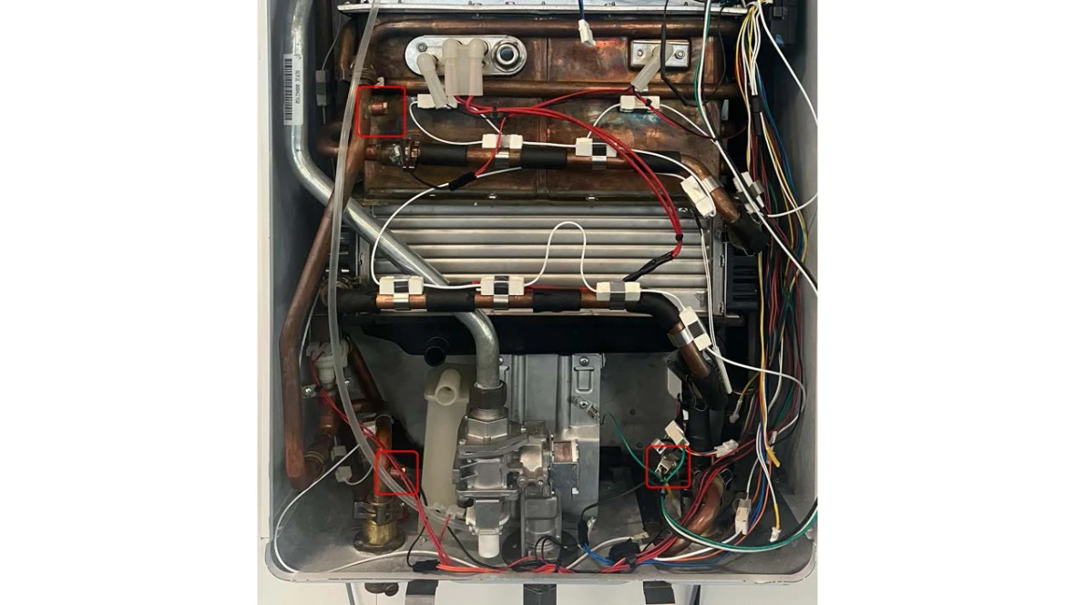
Results:
- If there were any loose or disconnected wires, re-seat the connections to ensure they are tight and reset the error code.
- If there are any damaged wires, the component with the damaged wire will need to be replaced.
- If the wire connections are all tight and there is no damage to the wires, go to step 2.
Step 2. Check service menus for sensor temperature reading.
- Please reconnect the wire connection for the HMI control in the cover.
- Use the back button until P4 is on the display then hit the OK button.
- Use the down arrow until 0D is on the display and hit the OK button.
- Record the temperature readings for the Hex out, Inlet, and Outlet. Compare these readings with Ohms chart in manual.
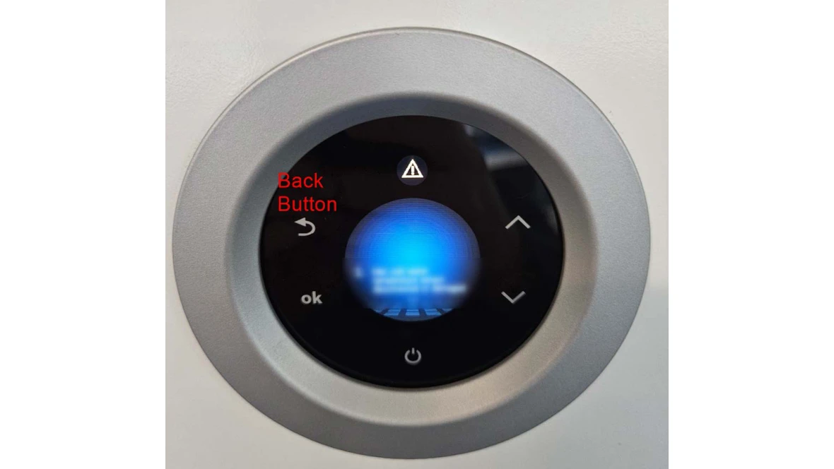
Results:
- If the temperature sensor reading(s) is 14, the control board does not see the sensors.
- A sensor, wire or control board could have failed
- If all of the temperature readings are something other than 14, and the error code still comes up, contact the Bosch technical support specialists.
A1 Error code
A1 Error code
Tools Needed
Digital Multi-meter
Hand Tools
Error Code Information
| Models | T9800SE160, T9800SE199, T9800SEO160, T9800SEO199, T9900SE160, T9900SE199, T9900iSE199 |
| Error Code | A1 |
| Error Code Meaning |
Cabinet Air Temp Too High (above 158 °F) |
| Possible Causes |
Faulty wiring harness Bad wire connections Failed Gasket |
Troubleshooting Steps
Step 1. Checking wire connections and condition.
- The air temp sensor is near the blower motor at the top of the unit.
- Ensure that the wire connection is tight to the sensor and the board.
- Ensure the wire is not damaged.
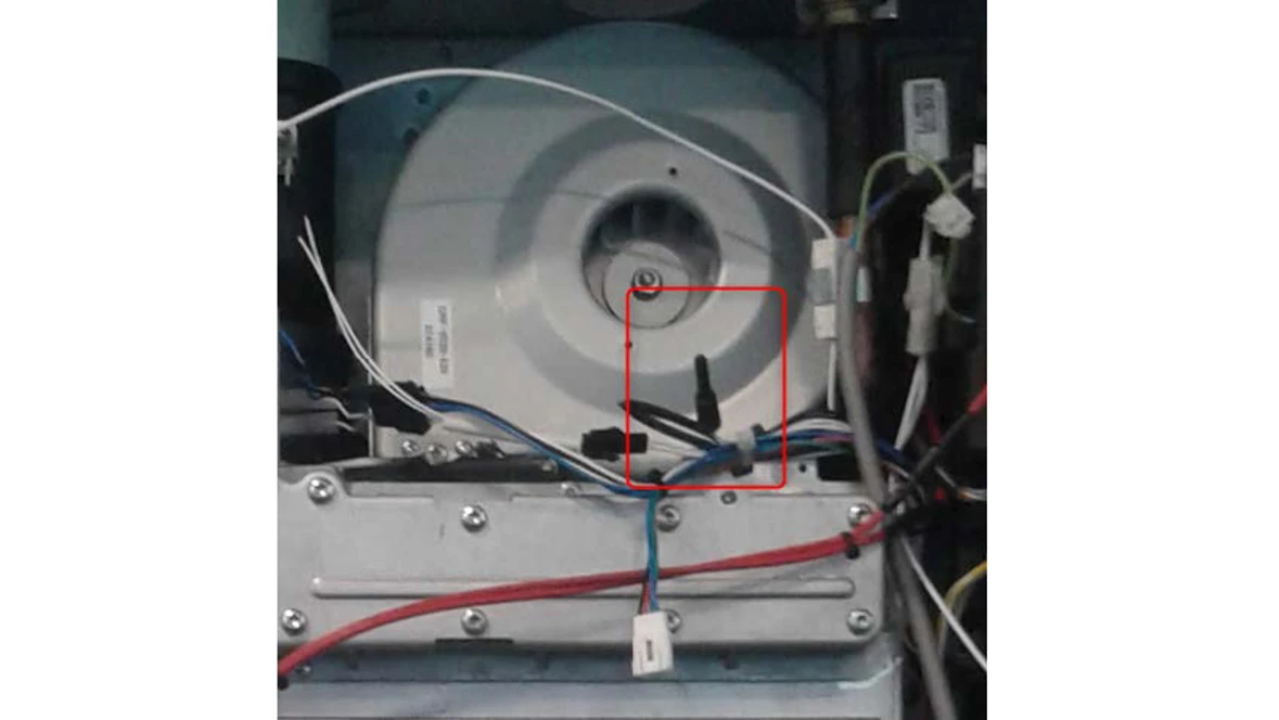
Results:
- If the wire connections are tight and the wire is undamaged, go to step 2.
- If the wire connections were not tight, please re-seat the connections. Reset the error code and if no further issues, move to step 2
- If the wire is damaged, the components will need to be replaced.
Step 2. Checking service menu for the sensor temperature reading.
- Hit the back button until P4 is on the display then hit the OK button.
- Use the down arrow until 0D is on the display and hit the OK button.
- Use the down arrow until "Ambient NTC" is displayed. Record temperature reading and compare with an independent temp sensor.
Results:
- If not connected the display will read -4° for "Ambient NTC"
- if the temperature reading is not above 158 °F and the error code wont reset, contact the Bosch technical support specialists.
A2 Error code
A2 Error code
Digital Multi-meter
Hand Tools
Error Code Information
| Models | T9800SE160, T9800SE199, T9800SEO160, T9800SEO199, T9900SE160, T9900SE199, T9900iSE199 |
| Error Code | A2 |
| Error Code Meaning |
External temp sensors not detected |
| Possible Causes |
Bad wire harness connection Broken sensor Wrong setting |
Troubleshooting Steps
Step 1. Confirm the application
- Is this machine set up for a tank loading application?
- If yes, you will need to confirm the unit is setup correctly under "A1 Recirculations"
- Use the back button on the display to show "P4".
- Use the down arrow to show "SA" and hit the "OK" button.
- Use the down arrow to show "A1 Reciruclations" and hit the "OK" button.
- It should show "Tank loading" at this point.
- Make sure the correct tank sensor was chosen
-
- If no, you will need turn off the setting under "A1 Recirculations"
- Use the back button on the display to show "P4".
- Use the down arrow to show "SA" and hit the "OK" button.
- Use the down arrow to show "A1 Reciruclations" and hit the "OK" button.
- It should show "House Recirculation" at this point.
- Use the down button to go to "Off" and hit the "OK" button.
Results:
- If the unit is installed with and setup for tank loading and they cannot reset the error code, contact the Bosch technical support specialists.
- If the unit is not installed for a tank loading application, ensure the "A1 Recirculations" is set to "Off". If the error has gone away, the issue has been resolved.
- If the unit is not installed for a tank loading application and "A1 Reciruclations" has been set to off but the error won't go away, contact the Bosch technical support specialists.
A3 Error code
A3 Error code
Digital Multi-meter
Hand Tools
Error Code Information
| Models | T9800SE160, T9800SE199, T9800SEO160, T9800SEO199, T9900SE160, T9900SE199, T9900iSE199 |
| Error Code | A3 |
| Error Code Meaning |
Exhaust temp sensor not detected |
| Possible Causes |
Bad wire harness connection Faulty Sensor |
Troubleshooting Steps
Step 1. Check sensor wiring
- The exhaust temp sensor is located at the top of the unit, plugged into the exhaust pipe.
- Ensure that all wire connections are tight and that the wires are undamaged.
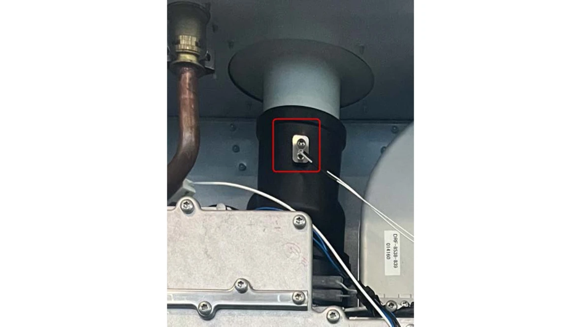
Results:
- If the wire connections are not tight, please re-seat the connections. If the error goes away the problem has been solved.
- If the wires were damaged, the wire harness will need to be replaced.
- If the wire connections are tight and the wire is undamaged, go to step 2.
Step 2. Confirm service menu reading
- Use the "Back" button on the HMI display to show "P4".
- Use the down arrow to display "0D" and then hit the "OK" button.
- Use the down arrow to display "Exhaust Gas NTC" and read off the temperature reading.
Results:
- If the temperature reading for the "Exhaust Gas NTC" is 14, it's a faulty sensor or connection.
- If the temperature reading for the "Exhaust gas NTC" is something other than 14, contact the Bosch technical support specialists.
A4 Error code
A4 Error code
Digital Multi-meter
Hand Tools
Error Code Information
| Models | T9800SE160, T9800SE199, T9800SEO160, T9800SEO199, T9900SE160, T9900SE199, T9900iSE199 |
| Error Code | A4 |
| Error Code Meaning | Cabinet air sensor not detected |
| Possible Causes |
Bad wiring harness/connection Faulty sensor |
Troubleshooting Steps
Step 1. Check wiring to sensor
- Locate the cabinet air sensor near the blower motor.
- Once located, ensure the wires are connected to the board tightly and that they are undamaged.
Results:
- If connected the code will reset and problem is solved
- If the wire is damaged or the connection to the board can't be tightened, the wire harness or connector may be faulty
- If the wire is undamaged and the connection to the board is tight, go to step 2.
Step 2. Checking service menu for the temperature sensor reading.
- Use the back button until P4 is on the display then hit the OK button.
- Use the down arrow until 0D is on the display and hit the OK button.
- Use the down arrow until "Ambient NTC" is displayed. Record this reading.
Results:
- If the temperature reading is -4°F, the temperature sensor is faulty or not connected.
- if the temperature reading is something other than -4°F and the error code wont reset, contact the Bosch technical support specialists.
A5 Error code
A5 Error code
Digital Multi-meter
Hand Tools
Error Code Information
| Models | T9800SE160, T9800SE199, T9800SEO160, T9800SEO199, T9900SE160, T9900SE199, T9900iSE199 |
| Error Code | A5 |
| Error Code Meaning |
Condensing HX sensor not detected |
| Possible Causes |
Bad wire harness/connection Faulty Sensor |
Troubleshooting Steps
Step 1. Check sensor wiring
- On top right corner of the stainless steel heat exchanger you should find the condensing HX sensor.
- Confirm that all wire connections are tight and that the wire is damaged.
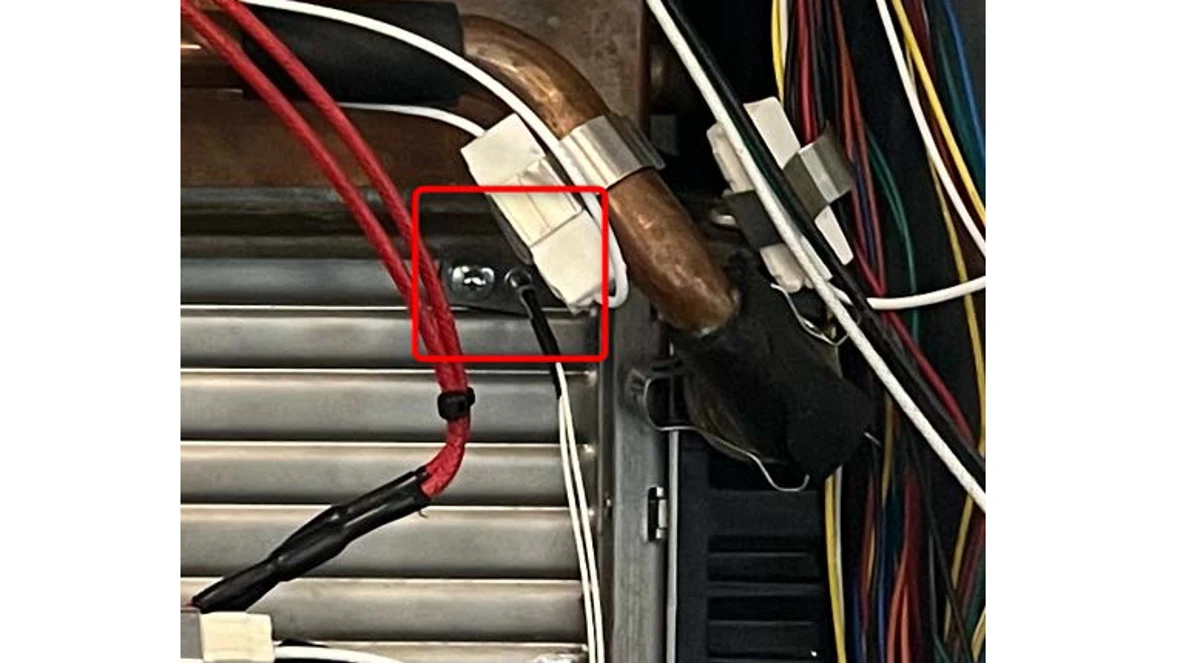
Results:
- If the wire connections are tight and the wire is undamaged, go to step 2.
- If the wire connections were loose and the unit will reset once they are re-seated, issue has been resolved.
- if the wire is damaged, it will need to be replaced.
Step 2. Checking service menu for the sensor temperature reading.
- Use the back button until P4 is on the display then hit the OK button.
- Use the down arrow until 0D is on the display and hit the OK button.
- Use the down arrow until "SS Hex NTC" is displayed. Record this reading.
Results:
- If the temperature reading is -32°F, the temperature sensor or connection is faulty.
- if the temperature reading is something other than -32°F and the error code wont reset, contact the Bosch Technical Support Specialists.
A6 Error code
A6 Error code
Digital Multi-meter
Hand Tools
Error Code Information
| Models | T9800SE160, T9800SE199, T9800SEO160, T9800SEO199, T9900SE160, T9900SE199, T9900iSE199 |
| Error Code | A6 |
| Error Code Meaning | CC-A6 |
| Possible Causes |
Bad wire harness/connection Faulty sensor |
Troubleshooting Steps
Step 1. Check sensor wiring
- The inlet temperature sensor is plugged into a black plastic housing in the bottom right. The black wires coming from the sensor will be connected to a pair of blue wires.
- Ensure that all wire connections are tight and that the wires are undamaged.
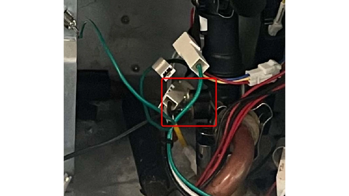
Results:
- If the wire connections are tight and the wire is undamaged, go to step 2.
- If the wire connections were loose, the unit will reset once they are re-seated and issue has been resolved.
- if the wire is damaged, it will need to be replaced.
Step 2. Checking service menu for the sensor temperature reading.
- Hit the back button until P4 is on the display then hit the OK button.
- Use the down arrow until 0D is on the display and hit the OK button.
- Use the down arrow until "Inlet NTC" is displayed. Record this reading.
Results:
- If the temperature reading is 14°F, the temperature sensor or connection is faulty.
- if the temperature reading is something other than 14°F and the error code wont reset, contact the Bosch technical support specialists.
A7 Error code
A7 Error code
Digital Multi-meter
Hand Tools
Error Code Information
| Models | T9800SE160, T9800SE199, T9800SEO160, T9800SEO199, T9900SE160, T9900SE199, T9900iSE199 |
| Error Code | A7 |
| Error Code Meaning |
Heat exchanger outlet water sensor not detected |
| Possible Causes |
Bad wiring harness/ connection Bad sensor |
Troubleshooting Steps
Step 1. Check sensor wiring
- The heat exchange outlet water temperature sensor is located on the left side of the primary (copper) heat exchanger.
- Ensure the wires connections are tight and that the wire is undamaged.
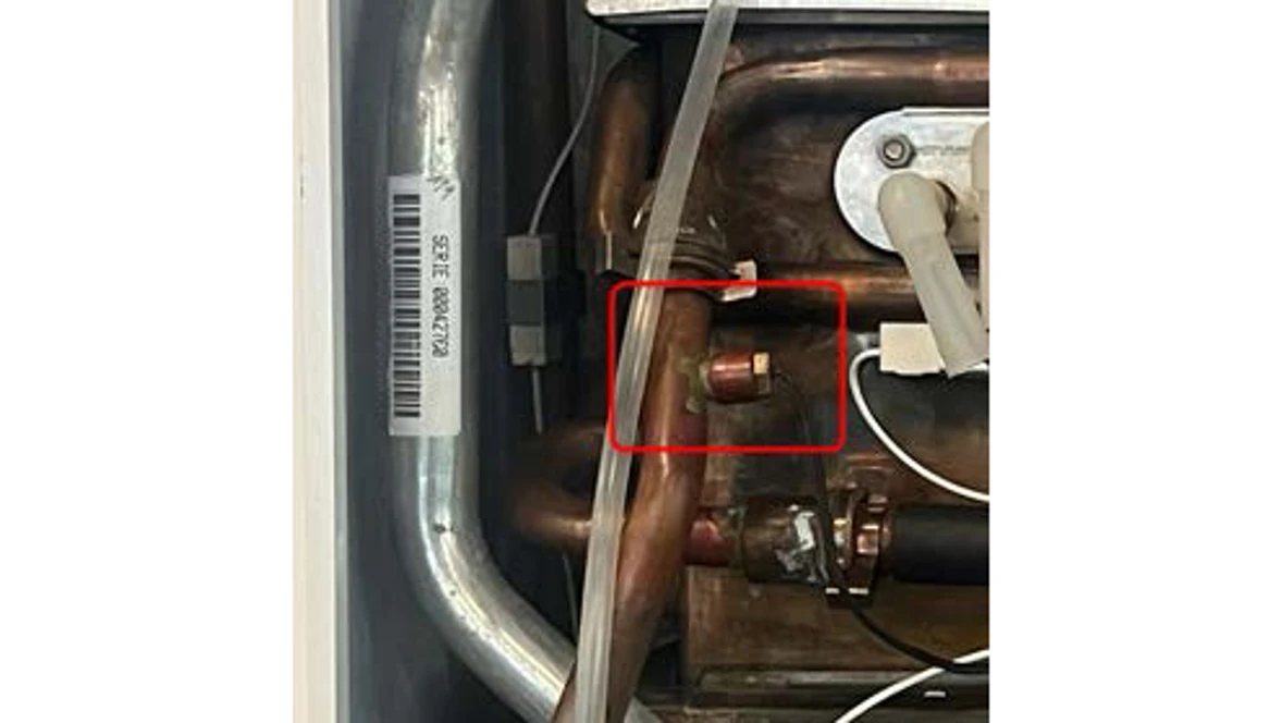
Results:
- If the wire connections are tight and the wire is undamaged, go to step 2.
- If the wire connections were loose and the unit will reset once they are re-seated.
- if the wire is damaged, it will need to be replaced.
Step 2. Checking service menu for the sensor temperature reading.
- Use the back button until P4 is on the display then hit the OK button.
- Use the down arrow until 0D is on the display and hit the OK button.
- Use the down arrow until "HEX Out NTC" is displayed. Record this reading
Results:
- If the temperature reading is 14°F, the temperature sensor or connection is faulty.
- if the temperature reading is something other than 14°F and the error code wont reset, transfer the call to the Bosch technical support specialists.
A8 Error code
A8 Error code
Digital Multi-meter
Hand Tools
Error Code Information
| Models | T9800SE160, T9800SE199, T9800SEO160, T9800SEO199, T9900SE160, T9900SE199, T9900iSE199 |
| Error Code | A8 |
| Error Code Meaning | Outlet water sensor not detected |
| Possible Causes |
Bad wire harnessconnection Faulty wire Bad sensor |
Troubleshooting Steps
Step 1. Check the inlet water temp sensor
- Check the wire connections to the outlet water sensor (bottom left corner of the unit) for tight fit and the wiring for any damaged wires.
Results:
- If the wiring is undamaged and the connection is tight, go to step 2.
- If the wiring connections are loose, disconnect them, re-seat the connection to ensure they are tight and reset the unit. If the error doesn't go away, go to step 2.
- If the wiring is damaged, they will need to replace the part that has the damaged portion of wiring (sensor or harness).
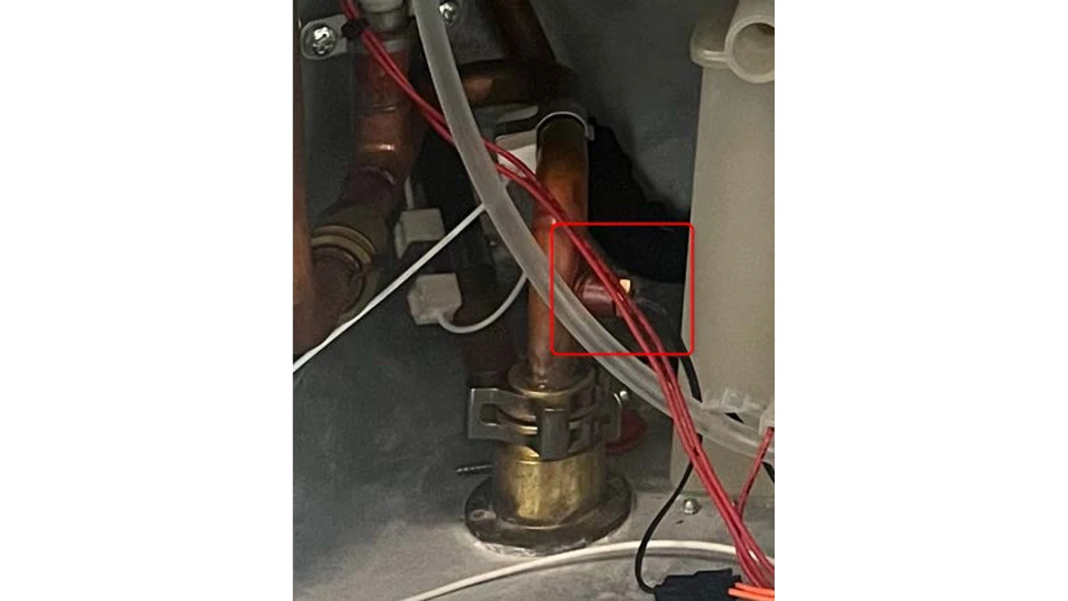
Step 2. Checking service menu for the sensor temperature reading.
- Have the caller hit the back button until P4 is on the display then hit the OK button.
- Have the caller use the down arrow until 0D is on the display and hit the OK button.
- Have the caller use the down arrow until "Outlet NTC" is displayed. Record this reading.
Results:
- If the temperature reading is 14°F, the temperature sensor or connection is faulty.
- if the temperature reading is something other than 14°F and the error code wont reset, contact the Bosch Technical Support Specialists.
A9 Error code
A9 Error code
Digital Multi-meter
Hand Tools
Error Code Information
| Models | T9800SE160, T9800SE199, T9800SEO160, T9800SEO199, T9900SE160, T9900SE199, T9900iSE199 |
| Error Code | A9 |
| Error Code Meaning | Output power too low |
| Possible Causes |
Bad sensor Gas supply is too low |
Troubleshooting Steps
Step 1. Reset the error code.
- If the error is on the screen currently, reset the code by holding the power button for 3 seconds.
Results:
- If the error code resets and they are able to get hot water without issue, it may have been a random drop in gas pressure.
- If the error code comes back when trying to get hot water, gas pressure will need to be checked.
Step 2. Checking gas pressure.
- Shut off gas to the unit.
- Locate the gas port on the bottom center of the unit.
- Use a screw driver to back out the screw two full turns.
- Connect their manometer onto the gas port. The hose from their manometer should go over the gas port.
- When the hose from the manometer is seated tightly on the gas port, turn the gas supply back on.
- Once the gas supply is on, record the pressure reading on their manometer. It should be measuring in inches of water column (WC).
- With manometer still connected, turn on multiple faucets in the home, record gas pressure reading.
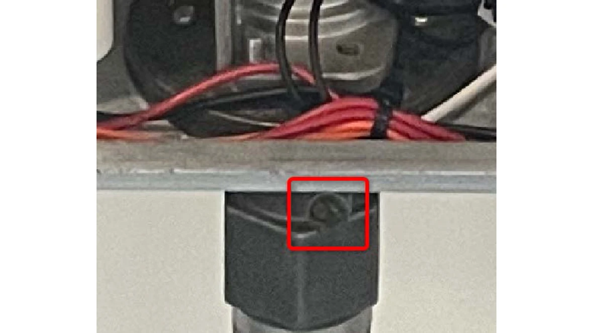
Results:
- The readings for the gas pressure should be within the ranges noted below:
- Natural Gas (NG): 3.5"-10.5" WC
- Liquid Propane (LP): 8"-13" WC
- If the pressure is not within the ranges noted, there is an issue in their gas supply system. The tech or another professional will need to find the issue and resolve it.
- If the gas pressure is within range, and you are still getting this code, contact the Bosch technical support specialists.
AA Error code
AA Error code
Digital Multi-meter
Hand Tools
Manometer
Error Code Information
| Models | T9800SE160, T9800SE199, T9800SEO160, T9800SEO199, T9900SE160, T9900SE199, T9900iSE199 |
| Error Code | AA |
| Error Code Meaning | Condenser HX too hot |
| Possible Causes |
Bad wire connection Blocked Vent |
Troubleshooting Steps
Step 1. Confirm wire connections
- Check the wire connections to the sensor going into the condensing heat exchanger (top right corner of the heat exchanger).
Results:
- If the wire connections are not tight, disconnect them and reseat them to ensure they are tight.
- Reset the unit.
- If the error has gone away, issue has been resolved.
- If the error code has not gone away, go to step 2.
- If the wire connections are tight, go to step 2.
Step 2. Checking service menu for the sensor temperature reading.
- Use the back button until P4 is on the display then hit the OK button.
- Use the down arrow until 0D is on the display and hit the OK button.
- Use the down arrow until "SS Hex NTC" is displayed. Record this reading.
Results:
- If the temperature reading is 32°F, the control does not see the sensor, it may be faulty.
- if the temperature reading is something other than 32°F and the error code wont reset, contact the technical support specialists.
AD Error code
AD Error code
Digital Multi-meter
Hand Tools
Manometer
Error Code Information
| Models | T9800SE160, T9800SE199, T9800SEO160, T9800SEO199, T9900SE160, T9900SE199, T9900iSE199 |
| Error Code |
AD Note: AD is a status code |
| Error Code Meaning | Appliance has derated itself |
| Possible Causes |
Bad venting Dirty Combustion Vent blockage |
Troubleshooting Steps
Step 1. Noting the elevation
- Check the elevation above sea level where the machine is installed. Note: machines above 2,000ft ASL can have AD codes due to altitude.
Step 2. Check the fan for the metal screen or paper filter.
- If there is one, it will be a metal mesh filter or pleated paper filter.
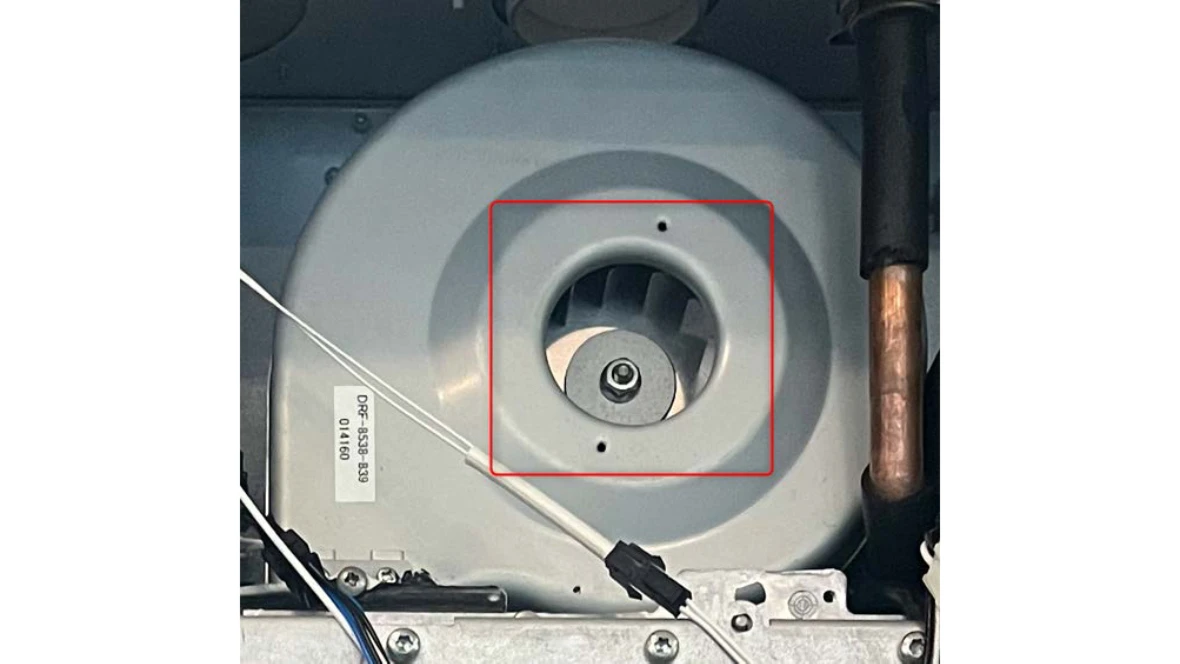
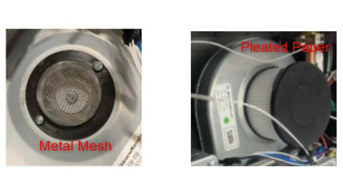
Results:
- If the metal filter, verify it is clean and reset code. If the code comes back, go to step 3.
- If the pleated paper filter, remove the black cap, reset the code and see if the code comes back.
- If the code doesn't come back, replace the filter.
- If the code does come back, go to step 3.
- If there is no filter, go to step 3.
Step 3. Contact the Bosch technical support specialists.
BB / BC Error code
BB / BC Error code
Digital Multi-meter
Basic hand tools (wrench, screwdriver, etc.)
Manometer
Error Code Information
| Models | T9800SE160, T9800SE199, T9800SEO160, T9800SEO199, T9900SE160, T9900SE199, T9900iSE199 |
| Error Code | BB / BC |
| Error Code Meaning |
There is a combustion issue somewhere and the unit has to adjust itself to compensate for it. |
| Possible Causes |
Gas supply issue Dirty Combustion |
Troubleshooting Steps
Step 1. Confirm gas type
- Check what gas type the unit is using: NG (natural gas) or LP (liquid propane).
Step 2. Check gas pressure
- Shut off the gas supply to the unit and then attach the manometer to the port on the gas pipe at the bottom of the unit. Once the manometer is tightly fitted to the port, they can turn the gas back on to the unit.
- Record pressure reading
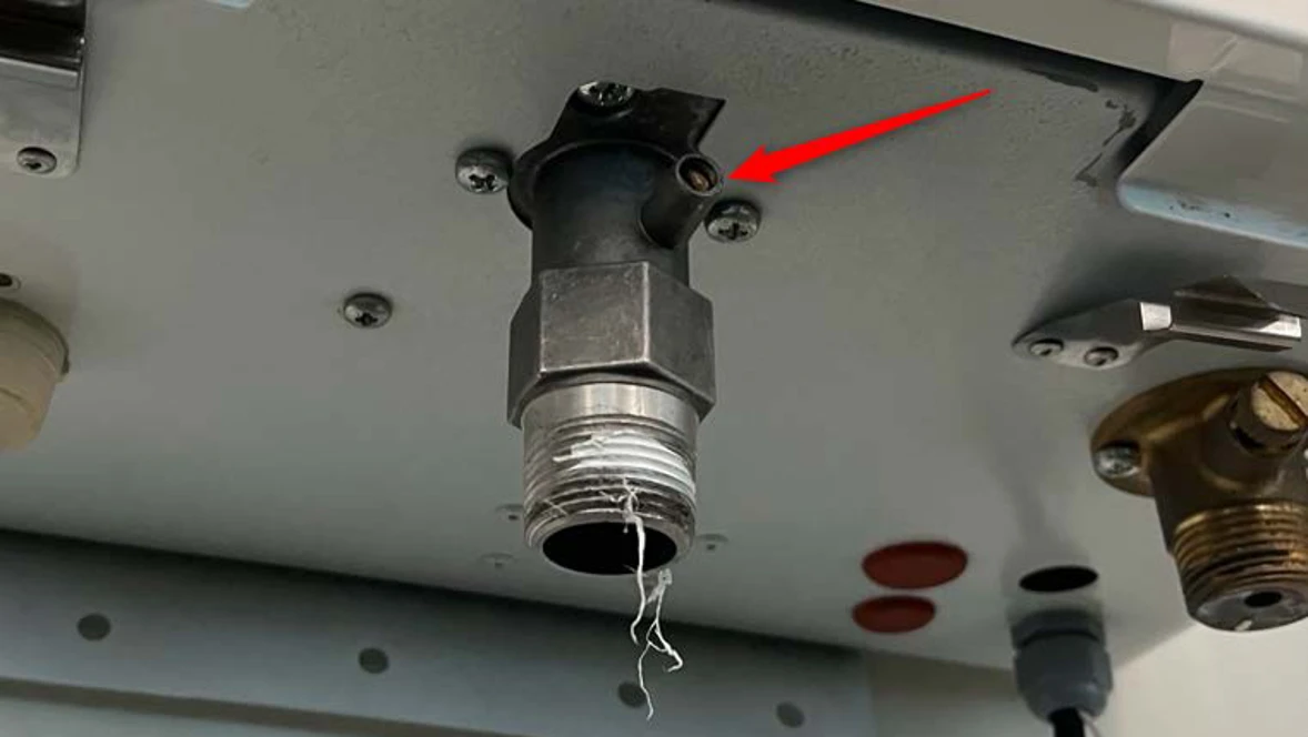
Results:
- If the gas pressure is not in the ranges noted below, they have a gas supply issue they will need to resolve. NOTE: This has nothing to do with the unit, they need to look at the gas supply system.
- If the gas pressure is within the ranges noted below, move to the next step.
- NG: 3.5-10.5" WC (inches of water column)
- LP: 8-13" WC (inches of water column)
Step 3. Checking gas pressure during ignition attempt.
- With the manometer still connected, have them open a hot water tap so the unit tries to fire.
- There should be a drop in gas pressure at the test port
- Note the lowest gas pressure reading while the unit tries to fire.
Results:
- If the gas drops below the minimum allowable pressure (NG = 3.5" WC, LP = 8"WC), they have a gas supply issue they will need to resolve. NOTE: This has nothing to do with the unit, they need to look at the gas supply system.
- If the gas pressure stays above the minimum allowable pressure (NG = 3.5" WC, LP = 8"WC), follow the steps in the manual to adjust the gas and air mixture.
- Contact the Bosch technical service specialist for assistance
C1 Error code
C1 Error code
Digital Multi-meter
Hand Tools
Manometer
Error Code Information
| Models | T9800SE160, T9800SE199, T9800SEO160, T9800SEO199, T9900SE160, T9900SE199, T9900iSE199 |
| Error Code | C1 |
| Error Code Meaning | Vent blockage detected |
| Possible Causes |
Venting too long Blockage in the machine or the venting |
Troubleshooting Steps
Step 1. Checking the venting
- Check the venting to see if free of debris
- Confirm vent length and compare to limits within the manual.
Results:
- If the venting is not clear, remove the debris and reset the code. If the code does not go away, contact Bosch technical support specialists.
- If the venting is clear, and not longer than the requirements in the manual, contact Bosch technical support specialists.
C2 Error code
C2 Error code
Digital Multi-meter
Hand Tools
Manometer
Error Code Information
| Models | T9800SE160, T9800SE199, T9800SEO160, T9800SEO199, T9900SE160, T9900SE199, T9900iSE199 |
| Error Code | C2 |
| Error Code Meaning | Vent blockage detected |
| Possible Causes |
Venting is too long Blockage in the machine or venting |
Troubleshooting Steps
Step 1. Checking the venting
- Check the venting to see if free of debris
- Confirm vent length and compare to limits within the manual.
Results:
- If the venting is not clear, remove the debris and reset the code. If the code does not go away, contact Bosch technical support specialists.
- If the venting is clear, and not longer than the requirements in the manual, contact Bosch technical support specialists.
C3 Error code
C3 Error code
Digital Multi-meter
Hand Tools
Error Code Information
| Models | T9800SE160, T9800SE199, T9800SEO160, T9800SEO199, T9900SE160, T9900SE199, T9900iSE199 |
| Error Code | C3 |
| Error Code Meaning | No flow with recirculation |
| Possible Causes |
Blockage in the plumbing Wrong settings |
Troubleshooting Steps
Step 1. Check application
- Check if the plumbing and install are set up for recirculation.
Results:
- If yes, check system for blockages or restrictions
- If no, go to step 2.
Step 2. Change settings.
- Use the back arrow on the HMI until they see P4.
- Use the down arrow until they see SA, then hit OK.
- Use the down arrow until they see A1, then hit OK.
- Use the down arrow until they see OFF, then hit OK.
- Reset the code
Results:
- Reset the code.
- If there was no recirculation and settings have been changed, issue is all set
- If no restrictions and code keeps reoccurring, contact the technical support specialists.
C5 Error code
C5 Error code
Digital Multi-meter
Hand Tools
Error Code Information
| Models | T9800SE160, T9800SE199, T9800SEO160, T9800SEO199, T9900SE160, T9900SE199, T9900iSE199 |
| Error Code | C5 |
| Error Code Meaning | Bypass valve failure |
| Possible Causes |
Failed part Disconnected wire |
Troubleshooting Steps
Step 1. Check wire connections and inspect valve
-
- Check the two red wire connections to the by-pass valve located in the bottom left corner of the unit.
- Disconnection them and reconnect them to ensure a tight fit.
Results:
- If yes, check system for blockages or restrictions
- If no, go to step 2.
Step 2. Change settings.
- Use the back arrow on the HMI until they see P4.
- Use the down arrow until they see SA, then hit OK.
- Use the down arrow until they see A1, then hit OK.
- Use the down arrow until they see OFF, then hit OK.
- Reset the code
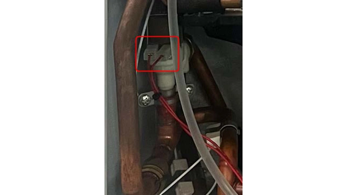
Step 2. Check the by-pass valve
- Visually inspect the by-pass solenoid valve for damage.
- If damaged, the valve will need to be replaced
- If not damaged, move to next step
Results:
- If the wire connections are not tight, disconnection them and reconnect them to ensure a tight fit.
- Reset the unit and use hot water to test the machine, if the error does not come back, issue has been resolved.
- Reset the unit and use hot water to test the machine, if the error comes back, bypass valve will need to be replaced.
C7 Error code
C7 Error code
Digital Multi-meter
Hand Tools
Error Code Information
| Models | T9800SE160, T9800SE199, T9800SEO160, T9800SEO199, T9900SE160, T9900SE199, T9900iSE199 |
| Error Code | C7 |
| Error Code Meaning | Fan not detected |
| Possible Causes |
Failed Part Bad wiring |
Troubleshooting Steps
Step 1. Check wiring connection
- Locate the wire connections shown below (blue, brown, yellow and red wires). They should disconnect and then reconnect them.
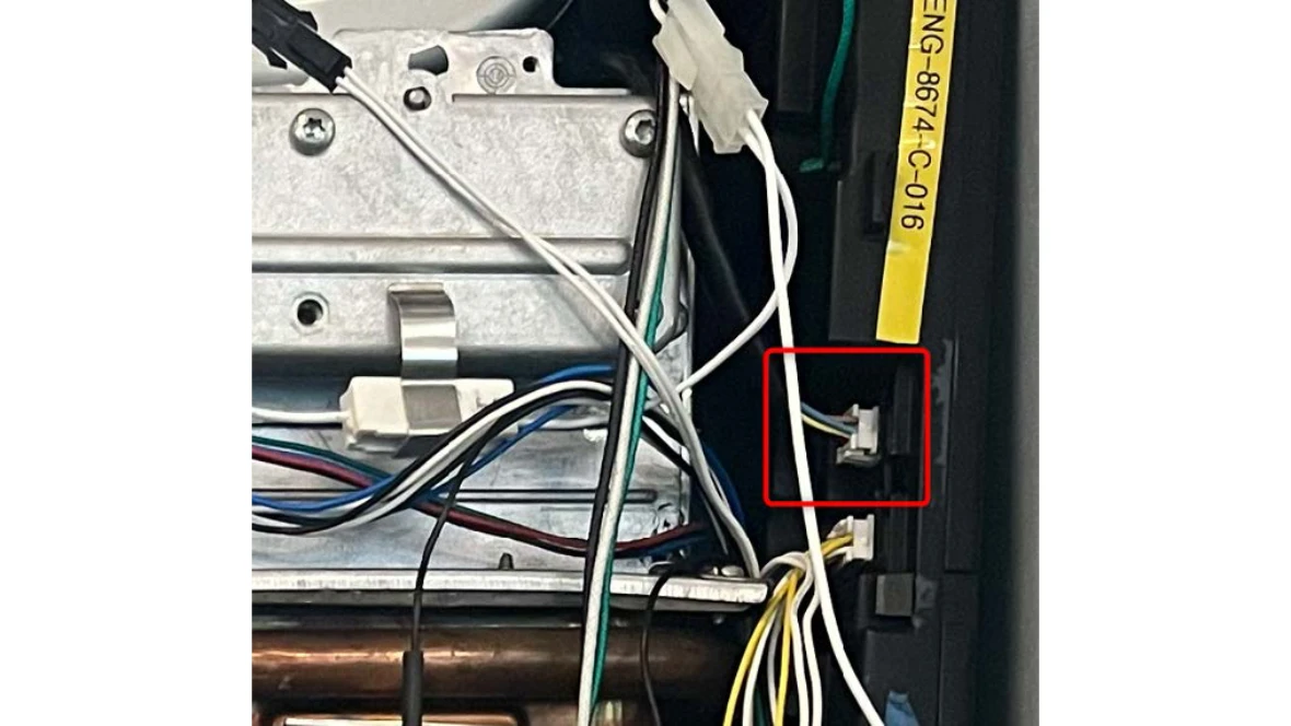
Results:
- Reset the unit.
- If the error doesn't come back, issue has been resolved
- If the error comes back, the fan should be replaced, contact the Bosch technical support specialists for further assistance.
C8 Error code
C8 Error code
Digital Multi-meter
Hand Tools
Error Code Information
| Models | T9800SE160, T9800SE199, T9800SEO160, T9800SEO199, T9900SE160, T9900SE199, T9900iSE199 |
| Error Code | C8 |
| Error Code Meaning | Issue with Motor on Water Valve |
| Possible Causes |
Failed Part Bad wiring |
Troubleshooting Steps
Step 1. Reset the error
- Reset the unit by holding the power button for 3 seconds.
- Check for any grinding or humming noises coming from the water valve
- Grinding/humming noises are a sign the water valve needs to be replaced
Results:
- If the error doesn't come back, the issue is likely resolved.
- If the error comes back, the water valve will need to be replaced. Contact the Bosch technical support specialists further assistance.
CA Error code
CA Error code
Digital Multi-meter
Hand Tools
Error Code Information
| Models | T9800SE160, T9800SE199, T9800SEO160, T9800SEO199, T9900SE160, T9900SE199, T9900iSE199 |
| Error Code | CA |
| Error Code Meaning | Too much water flow through unit. |
| Possible Causes | Too much waterflow through unit. |
Troubleshooting Steps
Step 1. Checking service menu for the flow rate.
- Use the back button until P4 is on the display then hit the OK button.
- Use the down arrow until 0D is on the display and hit the OK button.
- Use the down arrow until "Flow Rate" is displayed. Record reading.
- Compare reading with the flow at the tap
- If flow reading is not accurate, contact the Bosch technical support specialists
CE / CF Error codes
CE / CF Error codes
Digital Multi-meter
Basic hand tools (wrench, screwdriver, etc.)
Manometer
Error Code Information
| Models | T9800SE160, T9800SE199, T9800SEO160, T9800SEO199, T9900SE160, T9900SE199, T9900iSE199 |
| Error Code | CF |
| Error Code Meaning | Vent blockage detected |
| Possible Causes |
Venting is too long Blockage in the machine or venting |
Troubleshooting Steps
Step 1. Checking the venting
- Check the venting to see if free of debris
- Confirm vent length and compare to limits in the manual.
Results:
- If the venting is not clear, remove the debris and reset the code. If the code does not go away, contact Bosch technical support specialists.
- If the venting is clear, and not longer than the requirements in the manual, perform the gas and air adjustment as instructed in the manual.
- Contact Bosch technical support specialist for further assistance.
E0 Error code
E0 Error code
Digital Multi-meter
Hand Tools
Error Code Information
| Models | T9800SE160, T9800SE199, T9800SEO160, T9800SEO199, T9900SE160, T9900SE199, T9900iSE199 |
| Error Code | E0 |
| Error Code Meaning | Control board issue |
| Possible Causes |
Faulty control board Power supply issue |
Troubleshooting Steps
Step 1. Reset the error code
- Hold the power button for 3 seconds to reset the error code.
Step 2. Checking power supply
- Check the Voltage and grounding at the outlet the unit is plugged into. Verify is is on it's own dedicated circuit.
- Check for any known power surges or power outages that have happened recently
Results:
- Any type of power fluctuation can cause this code
- If the unit is not on a dedicated circuit, that will need to be corrected to prevent the code.
- If the unit is plugged into the outlet by itself, or the code will not reset, contact the Bosch technical support specialists.
E1 Error code
E1 Error code
Digital Multi-meter
Hand Tools
Error Code Information
| Models | T9800SE160, T9800SE199, T9800SEO160, T9800SEO199, T9900SE160, T9900SE199, T9900iSE199 |
| Error Code | E1 |
| Error Code Meaning |
Outlet Water temp sensor overheat (>194°F) |
| Possible Causes |
Faulty temperature sensor Failed by-pass valve |
Troubleshooting Steps
Step 1. Checking service menu for the sensors temperature reading.
- Use the back button until P4 is on the display then hit the OK button.
- Use the down arrow until 0D is on the display and hit the OK button.
- Use the down arrow until "Hex Out", "Inlet" and "Outlet" is displayed. Record the "Outlet NTC" and compare with Ohms chart in manual.
Results:
- If the readings are similar the water is overheating and the code is shutting down the machine like it should be
- We need to figure out why it is overheating, contact Bosch Technical Support Specialist for assistance.
- If the readings are different, the machine is not getting an accurate reading from the sensor, contact Bosch Technical Support Specialist for assistance.
E3 Error code
E3 Error code
Digital Multi-meter
Hand Tools
Error Code Information
| Models | T9800SE160, T9800SE199, T9800SEO160, T9800SEO199, T9900SE160, T9900SE199, T9900iSE199 |
| Error Code | E3 |
| Error Code Meaning | Flue gas temp sensor overheat (>145°F) |
| Possible Causes |
Blocked vent Faulty temperature sensor |
Troubleshooting Steps
Step 1. Checking service menu for the sensor temperature reading.
- Use the back button until P4 is on the display then hit the OK button.
- Use the down arrow until 0D is on the display and hit the OK button.
- Use the down arrow until "Exhaust Gas NTC" is displayed. Record this temperature and compare with Ohms chart in manual.
Results:
- If the readings are similar, the exhaust is overheating and the code is shutting down the machine like it should be
- We need to figure out why it is overheating, contact Bosch Technical Support Specialist for assistance.
- If the readings are different, the machine is not getting an accurate reading from the sensor, contact Bosch Technical Support Specialist for assistance.
E4 Error code
E4 Error code
Digital Multi-meter
Hand Tools
Error Code Information
| Models | T9800SE160, T9800SE199, T9800SEO160, T9800SEO199, T9900SE160, T9900SE199, T9900iSE199 |
| Error Code | E4 |
| Error Code Meaning | Cabinet air sensor too hot (>176°F) |
| Possible Causes |
Faulty sensor Unit is overheating |
Troubleshooting Steps
Step 1. Checking wire connections
- Check the wire connections the cabinet temperature sensor . Look for any damage to the wire or a loose connection.
Results:
- If the wire is damaged, the cable harness will need to be replaced.
- If the wire connection is loose, disconnect and then re-seat the connection. Reset the unit and go to step 2.
Step 2. Checking service menu for the sensor temperature reading.
- Hit the back button until P4 is on the display then hit the OK button.
- Use the down arrow until 0D is on the display and hit the OK button.
- Use the down arrow until "Ambient NTC" is displayed. Record this reading.
- Compare recorded temperature to an independent reading of the air inside the cabinet
Results:
- If readings are similar, the reading is likely accurate, we will need to see why the machine is overheating
- Check gaskets around the combustion chamber.
- Check combustion chamber for any holes or air leaking
- Verify the exhaust is properly connected inside the machine
- If readings are different, sensor may be faulty. Sensor is part of wire harness and may need to be replaced
- Contact Bosch Technical Support specialist for further assistance
E5 Error code
E5 Error code
Digital Multi-meter
Hand Tools
Error Code Information
| Models | T9800SE160, T9800SE199, T9800SEO160, T9800SEO199, T9900SE160, T9900SE199, T9900iSE199 |
| Error Code | E5 |
| Error Code Meaning |
Condensing heat exchanger sensor overheating |
| Possible Causes |
Blockage in venting Gas pressure too high Combustion not set correctly Bad sensor |
Troubleshooting Steps
Step 1. Reset the error code
- Hold the power button for 3 seconds to reset the code.
Step 2. Confirm wire connections
- Check the wire connections to the sensor going into the condensing heat exchanger (top right corner of the heat exchanger).
Results:
- If the wire connections are not tight, disconnect them and re-seat them to ensure they are tight.
- Reset the unit and move to step 2.
- If the wire connections are tight, go to step 2.
Step 2. Checking service menu for the sensor temperature reading.
- Hit the back button until P4 is on the display then hit the OK button.
- Use the down arrow until 0D is on the display and hit the OK button.
- Use the down arrow until "SS Hex NTC" is displayed. Record this reading and compare with Ohms chart in manual.
Results:
- If the readings are similar, the "SS Hex" sensor is overheating and the code is shutting down the machine like it should be
- We need to figure out why it is overheating, contact Bosch Technical Support Specialist for assistance.
- If the readings are different, the machine is not getting an accurate reading from the sensor, contact Bosch Technical Support Specialist for assistance.
E7 Error code
E7 Error code
Digital Multi-meter
Hand Tools
Error Code Information
| Models | T9800SE160, T9800SE199, T9800SEO160, T9800SEO199, T9900SE160, T9900SE199, T9900iSE199 |
| Error Code | E7 |
| Error Code Meaning | Control board issue |
| Possible Causes |
Bad control Power supply issue |
Troubleshooting Steps
Step 1. Reset the error code
- Hold the power button for 3 seconds to reset the error code.
- Check the Failure History (FH) in the service menu
- Use the back button until P4 is on the display then hit the OK button.
- Use the down arrow until FH is on the display and hit the OK button.
- Machine will store up to 10 codes, check history to see if issue is repeated
Results:
- If the error code is a repeat issue, the control board will need to be replaced
- Part Number can be found here at The Aftermarket Resource Center
- If this is not a repeat issue, make note of the code and run machine
- If code were to come back, then control board should be replaced
E8 Error code
E8 Error code
Digital Multi-meter
Hand Tools
Error Code Information
| Models | T9800SE160, T9800SE199, T9800SEO160, T9800SEO199, T9900SE160, T9900SE199, T9900iSE199 |
| Error Code | E8 |
| Error Code Meaning | Control board issue |
| Possible Causes |
Control board issue Power supply issue |
Troubleshooting Steps
Step 1. Reset the error code
- Hold the power button for 3 seconds to reset the error code.
- Check the Failure History (FH) in the service menu
- Use the back button until P4 is on the display then hit the OK button.
- Use the down arrow until FH is on the display and hit the OK button.
- Machine will store up to 10 codes, check history to see if issue is repeated
Results:
- If the error code is a repeat issue, the control board will need to be replaced
- Part Number can be found here at The Aftermarket Resource Center
- If this is not a repeat issue, make note of the code and run machine
- If code were to come back, then control board should be replaced
E9 Error code
E9 Error code
Digital Multi-meter
Hand Tools
Error Code Information
| Models | T9800SE160, T9800SE199, T9800SEO160, T9800SEO199, T9900SE160, T9900SE199, T9900iSE199 |
| Error Code | E9 |
| Error Code Meaning | Thermal fuse is broken or the wiring harness is disconnected. |
| Possible Causes |
Faulty wiring harness Overheating |
Troubleshooting Steps
Step 1. Confirm wiring harness connection.
- The thermal fuse is in a loop of black wire as part of the wiring harness in the top portion of the unit. Re-seat the wire connection at the control board and reset the code (Hold power button for 3 seconds to reset)
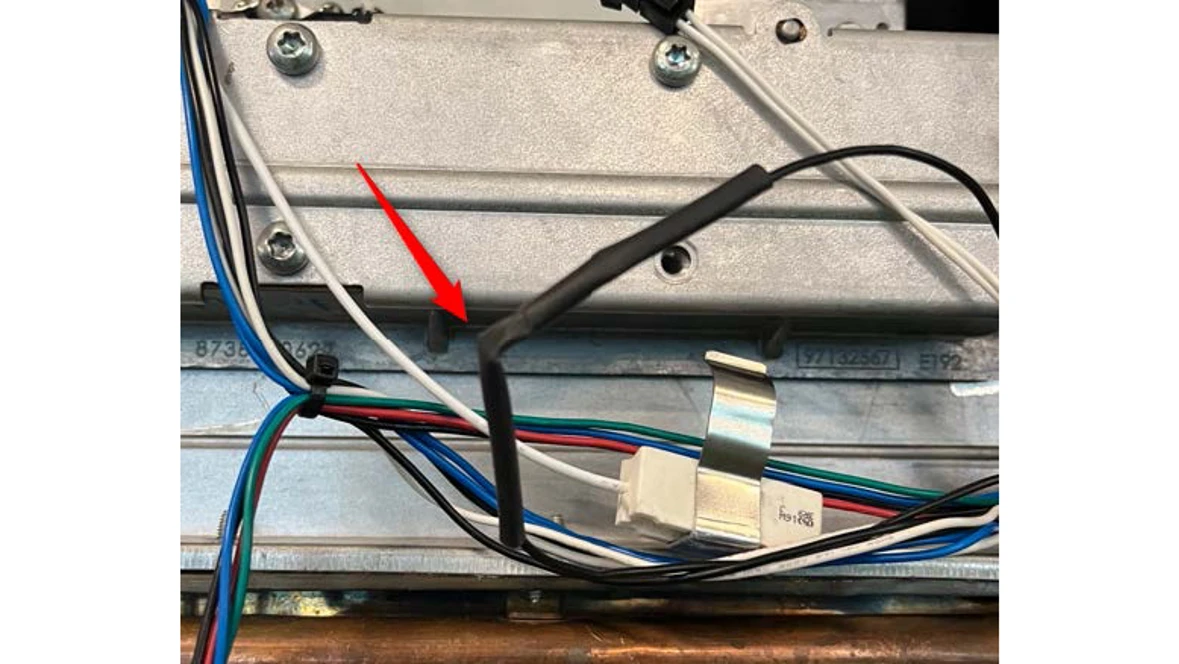
Results:
- If the code resets, it was likely a loose connection causing the code
- If the code does not reset, the fuse has broken and the wire harness needs to be replaced
- Part number can be found here at The Aftermarket Resource Center
- The fuse would have tripped for a reason, we need to find why. Check gaskets and heat exchanger for signs of overheating.
EA Error code
EA Error code
Digital Multi-meter
Hand Tools
Error Code Information
| Models | T9800SE160, T9800SE199, T9800SEO160, T9800SEO199, T9900SE160, T9900SE199, T9900iSE199 |
| Error Code | EA |
| Error Code Meaning | Failure to detect flame on startup |
| Possible Causes |
Gas supply issue Dirty Combustion Bad Combustion settings |
Troubleshooting Steps
Step 1. Reset the error code
- If the error code is on the screen, reset the error code by holding in the power button for 3 seconds.
Step 2. Confirm the gas type
- Check what gas type the unit is using: NG (natural gas) or LP (liquid propane).
Step 3. Check gas pressure
- Shut off the gas supply to the unit and then attach the manometer to the port on the gas pipe at the bottom of the unit. Once the manometer is tightly fitted to the port, they can turn the gas back on to the unit.
- Record pressure reading
Results:
- If the gas pressure is not in the ranges noted below, they have a gas supply issue they will need to resolve. NOTE: This has nothing to do with the unit, they need to look at the gas supply system.
- If the gas pressure is within the ranges noted below, move to the next step.
- NG: 3.5-10.5" WC (inches of water column)
- LP: 8-13" WC (inches of water column)
Step 4. Checking gas pressure during ignition attempt.
- With the manometer still connected, have them open a hot water tap so the unit tries to fire.
- There should be a drop in gas pressure at the test port
- Note the lowest gas pressure reading while the unit tries to fire.
Results:
- If the gas drops below the minimum allowable pressure (NG = 3.5" WC, LP = 8"WC), they have a gas supply issue they will need to resolve. NOTE: This has nothing to do with the unit, they need to look at the gas supply system.
- If the gas pressure stays above the minimum allowable pressure (NG = 3.5" WC, LP = 8"WC), and the machine fails to light, contact the Bosch technical service specialist for assistance
- If gas pressure does not drop when trying to light, the gas valve may not have opened, or there is a blockage.
EC Error code
EC Error code
Digital Multi-meter
Basic hand tools (wrench, screwdriver, etc.)
Manometer
Error Code Information
| Models | T9800SE160, T9800SE199, T9800SEO160, T9800SEO199, T9900SE160, T9900SE199, T9900iSE199 |
| Error Code | EC |
| Error Code Meaning | Flame loss during operation |
| Possible Causes |
Gas supply Dirty Combustion |
Troubleshooting Steps
Step 1. Reset the error code
- If the error code is on the screen, reset the error code by holding in the power button for 3 seconds.
Step 2. Confirm the gas type
- Check what gas type the unit is using: NG (natural gas) or LP (liquid propane).
Step 3. Check gas pressure
- Shut off the gas supply to the unit and then attach the manometer to the port on the gas pipe at
- the bottom of the unit. Once the manometer is tightly fitted to the port, they can turn the gas back on to the unit.
- Record pressure reading
Results:
- If the gas pressure is not in the ranges noted below, they have a gas supply issue they will need to resolve. NOTE: This has nothing to do with the unit, they need to look at the gas supply system.
- If the gas pressure is within the ranges noted below, move to the next step.
- NG: 3.5-10.5" WC (inches of water column)
- LP: 8-13" WC (inches of water column)
Step 4. Checking gas pressure during ignition attempt.
- With the manometer still connected, have them open a hot water tap so the unit tries to fire.
- There should be a drop in gas pressure at the test port
- Note the lowest gas pressure reading while the unit tries to fire.
Results:
- If the gas drops below the minimum allowable pressure (NG = 3.5" WC, LP = 8"WC), they have a gas supply issue they will need to resolve. NOTE: This has nothing to do with the unit, they need to look at the gas supply system.
- If the gas pressure stays above the minimum allowable pressure (NG = 3.5" WC, LP = 8"WC), follow the steps in the manual to adjust the gas and air mixture.
- Contact the Bosch technical service specialist for assistance
EF Error code
EF Error code
Digital Multi-meter
Basic hand tools (wrench, screwdriver, etc.)
Manometer
Error Code Information
| Models | T9800SE160, T9800SE199, T9800SEO160, T9800SEO199, T9900SE160, T9900SE199, T9900iSE199 |
| Error Code | EF |
| Error Code Meaning | Wrong gas type |
| Possible Causes |
Wrong gas type selected Not properly converted Gas pressure incorrect |
Troubleshooting Steps
Step 1. Reset the error code
- If the error code is on the screen, reset the error code by holding in the power button for 3 seconds. Go to step 2.
Step 2. Confirm the gas type
- Check what gas type the unit is using: NG (natural gas) or LP (liquid propane).
- Confirm gas type setting in the Technical Settings Service Menu (AU)
- Use back arrow to P4
- Use down arrow until AU
- Hit OK on AU, password is 1886
- After typing in password, check the "P7" setting and confirm that it matches the gas type the machine is using
- If NG, go to step 3.
- If LP, need to verify the LP kit is installed (gas restrictors in manifold).
- If LP restrictors are not installed, they will need to to properly convert the unit to LP fuel. Instructions are in the conversion kit manual.
- If restrictors are installed, go to step 3.
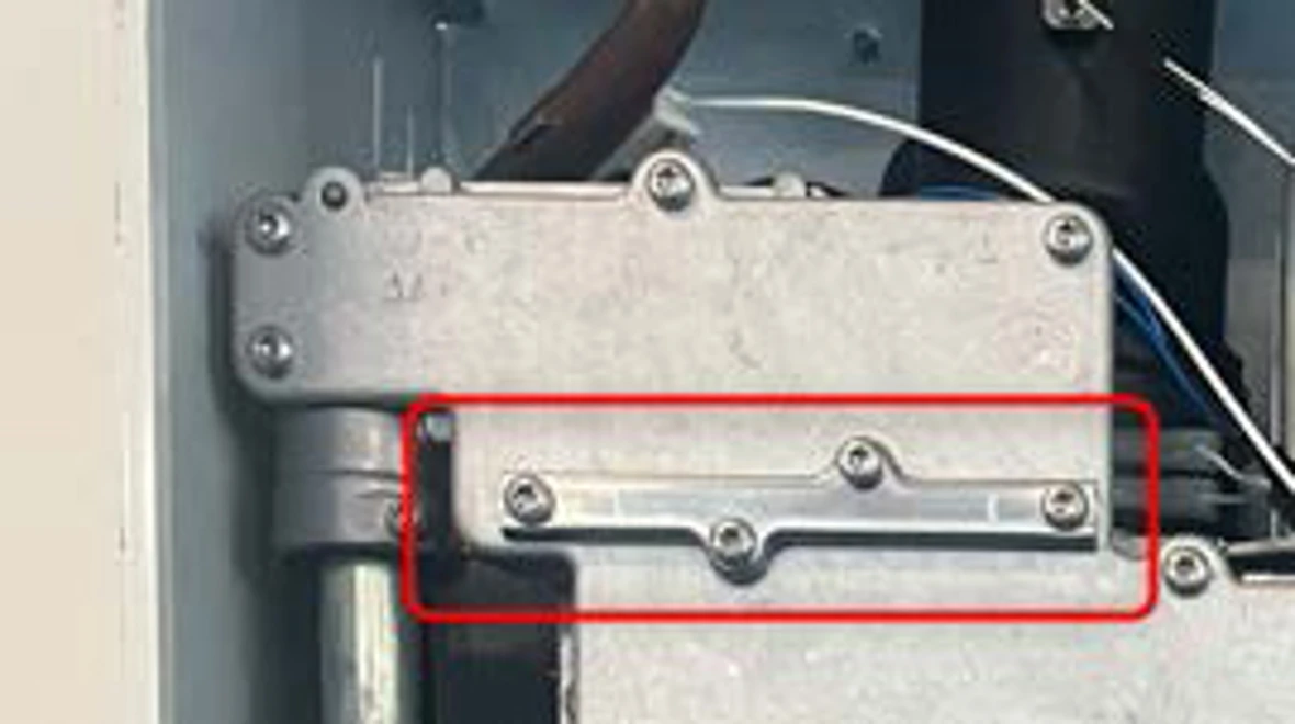
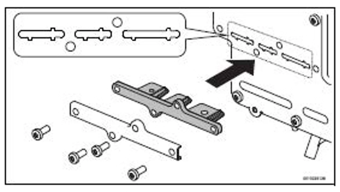
Step 3. Check gas pressure
- Shut off the gas supply to the unit and then attach the manometer to the port on the gas pipe at the bottom of the unit. Once the manometer is tightly fitted to the port, turn the gas back on to the unit and record the reading
Results:
- If the gas pressure is not in the ranges noted below, there is a gas supply issue that needs to be resolve. NOTE: This has nothing to do with the unit, they need to look at the gas supply system.
- If the gas pressure is within the ranges noted below, contact the Bosch technical support specialists.
- NG: 3.5-10.5" WC (inches of water column)
- LP: 8-13" WC (inches of water column)
F2 Error code
F2 Error code
Digital Multi-meter
Basic hand tools (wrench, screwdriver, etc.)
Error Code Information
| Models | T9800SE160, T9800SE199, T9800SEO160, T9800SEO199, T9900SE160, T9900SE199, T9900iSE199 |
| Error Code | F2 |
| Error Code Meaning | Control board issue |
| Possible Causes |
Bad Control Power Supply Issue |
Troubleshooting Steps
Step 1. Reset the error code
- Hold the power button for 3 seconds to reset the error code.
- Check the Failure History (FH) in the service menu
- Use the back button until P4 is on the display then hit the OK button.
- Use the down arrow until FH is on the display and hit the OK button.
- Machine will store up to 10 codes, check history to see if issue is repeated
Results:
- If the error code is a repeat issue, the control board will need to be replaced
- Part Number can be found here at The Aftermarket Resource Center
- If this is not a repeat issue, make note of the code and run machine
- If code were to come back, then control board should be replaced
F3 Error code
F3 Error code
Digital Multi-meter
Basic hand tools (wrench, screwdriver, etc.)
Error Code Information
| Models | T9800SE160, T9800SE199, T9800SEO160, T9800SEO199, T9900SE160, T9900SE199, T9900iSE199 |
| Error Code | F3 |
| Error Code Meaning | Control board issue |
| Possible Causes |
Bad Control Power Supply Issue |
Troubleshooting Steps
Step 1. Reset the error code and check history
- Hold the power button for 3 seconds to reset the error code.
- Check the Failure History (FH) in the service menu
- Use the back button until P4 is on the display then hit the OK button.
- Use the down arrow until FH is on the display and hit the OK button.
- Machine will store up to 10 codes, check history to see if issue is repeated
Results:
- If the error code is a repeat issue, the control board will need to be replaced
- Part Number can be found here at The Aftermarket Resource Center
- If this is not a repeat issue, make note of the code and run machine
- If code were to come back, then control board should be replaced
F7 Error code
F7 Error code
Digital Multi-meter
Basic hand tools (wrench, screwdriver, etc.)
Manometer
Error Code Information
| Models | T9800SE160, T9800SE199, T9800SEO160, T9800SEO199, T9900SE160, T9900SE199, T9900iSE199 |
| Error Code | F7 |
| Error Code Meaning | Ionization in standby |
| Possible Causes |
Bad Control Flame Sensor Grounded |
Troubleshooting Steps
Step 1. Reset the error code
- If the error code is on the screen, reset the error code by holding in the power button for 3 seconds. Once the error has been reset, go to step 2.
- If the code comes back, disconnect both flame sensors and reset the error code again
- If code will still not reset, contact Bosch technical support specialist
Step 2. Inspect the flame sensors
- Remove both flame sensors to clean and inspect the combustion chamber
- Look for any signs of moisture
- Look for anything that may come in contact with the flame sensor
Results:
- The flame sensor must not be in contact with anything
- Moisture is a sign the combustion chamber could be leaking
- If there is nothing coming in contact with the flame sensor and no moisture, flame sensors should be replaced
- Contact Bosch technical service specialist for further assistance.
F9 Error code
F9 Error code
Digital Multi-meter
Basic hand tools (wrench, screwdriver, etc.)
Manometer
Error Code Information
| Models | T9800SE160, T9800SE199, T9800SEO160, T9800SEO199, T9900SE160, T9900SE199, T9900iSE199 |
| Error Code | F9 |
| Error Code Meaning | Gas valve driver fault |
| Possible Causes |
Bad control Bad gas Valve |
Troubleshooting Steps
Step1. Check wire connections
- The gas valve is located at the bottom of the unit, verify the wires are plugged in correctly on both sides of the gas valve.
- Black and red wires on the left
- Black and black wires on the right
Results:
- If wires are not connected correctly, please fix. Reset the code and move on to next step
- If wires are connected correctly, move on to the next step
Step 2. Check gas valve resistance
- Set the meter to Ohms to check the resistance of each solenoid on the gas valve (Left and Right)
- Left Solenoid = 80Ω
- Right solenoid = 115Ω
- Reset Code
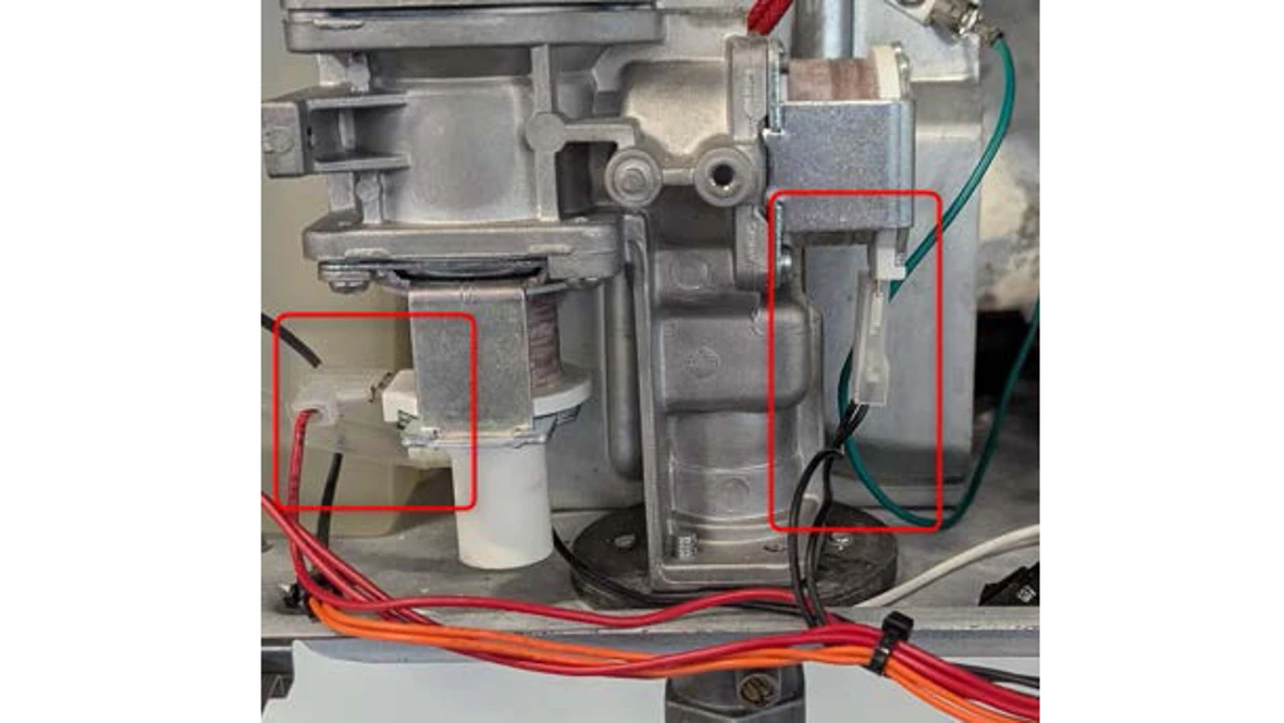
Results:
- If Solenoids are withing 10% of the expected values, the gas valve is good.
- If readings are outside of 10% of the expected value, gas valve should be replaced. The part number can be found here.
- If code resets, test operation of machine. If code does not reappear, issue has been resolved
- If the code will still not reset, it is likely the control board will need to be replaced.
FA Error code
FA Error code
Digital Multi-meter
Basic hand tools (wrench, screwdriver, etc.)
Manometer
Error Code Information
| Models | T9800SE160, T9800SE199, T9800SEO160, T9800SEO199, T9900SE160, T9900SE199, T9900iSE199 |
| Error Code | FA |
| Error Code Meaning |
Gas Leakage, Flame detected after operation |
| Possible Causes |
Grounded flame sensor, Bad flame sensor |
Troubleshooting Steps
Step 1. Reset the error code
- If the error code is on the screen, reset the error code by holding in the power button for 3 seconds. Once the error has been reset, go to step 2.
- If the code comes back, disconnect both flame sensors and reset the error code again
- If code will still not reset, contact Bosch technical support specialist^
Step 2. Inspect the flame sensors
- Remove both flame sensors to clean and inspect the combustion chamber
- Look for any signs of moisture
- Look for anything that may come in contact with the flame sensor
Results:
- The flame sensor must not be in contact with anything
- Moisture is a sign the combustion chamber could be leaking
- If there is nothing coming in contact with the flame sensor and no moisture, flame sensors should be replaced
- Contact Bosch technical service specialist for further assistance.
FC Error code
FC Error code
Digital Multi-meter
Basic hand tools (wrench, screwdriver, etc.)
Manometer
Error Code Information
| Models | T9800SE160, T9800SE199, T9800SEO160, T9800SEO199, T9900SE160, T9900SE199, T9900iSE199 |
| Error Code | FC |
| Error Code Meaning | Button pressed for too long |
| Possible Causes |
Button held down too long Moisture or debris in the display |
Troubleshooting Steps
Step 1. Reset the error code
- If the error code is on the screen, reset the error code by holding in the power button for 3 seconds.
Results:
- If the error resets and does not come back, its most likely a button was held down for too long.
- If the error doesn't reset or comes back, go to step 2.
Step 2. Checking the display
- Remove the display from the front cover. There are three clips that hold the two halves of the
- control together. Depress these clips to fully open the display control and look for any signs of moisture or debris.
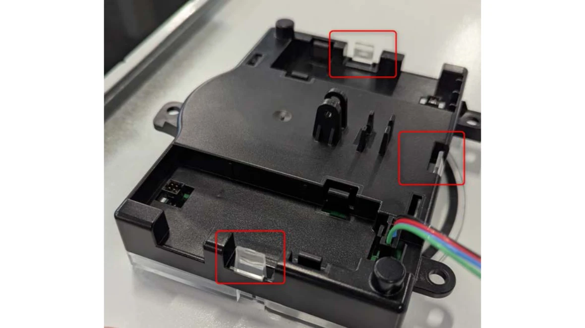
Results:
- If there is debris or moisture, remove it and ensure the control is clean and dry. Once back together, they should ensure that the error doesn't come back again.
- If the error does come back, they will need a new display control (HMI).
- If there is no debris or moisture and the error will not reset, contact technical support specialists.
Wifi Gateway
Wifi Gateway
If the caller is not onsite...
N/A
N/A
Error Code Information
| Models | T9800SE160, T9800SE199, T9800SEO160, T9800SEO199, T9900SE160, T9900SE199, T9900iSE199 |
| Error Code | CC-GEOS |
| Error Code Meaning |
The old Wi-Fi gateways are not compatible with the new Home Com Easy App. |
| Possible Causes | Wrong Wi-Fi module |
Troubleshooting Steps
Step 1. Verify the app they are using.
- If they were using the Bosch Water app but they are no longer able to connect with it and they have not purchased a new wifi module, go to step 2.
- If using the Home Com Easy app and they are having trouble connecting, confirm they have the right module.
- If the last four digits of the serial number on the wifi module is "1318", they have the new module. Please contact Bosch technical support specialists for further assistance.
- If the last four digits of the serial number on the wifi module is "4994", they have the old wifi module. Go to step 2.
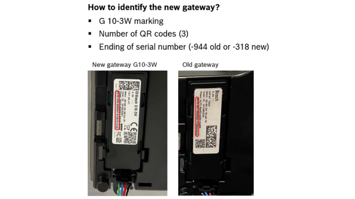
Results.
- If they have the right module, they should be able to connect to the Home Com Easy app.
- Contact Bosch Technical Support Specialist for further assistance
- If they do not have right module, the new one is no longer available. They will be unable to use the Home Com Easy app.